UsingTheControlPanel
The Bendix G-15 had a minimalist Control Panel on the front of its cabinet. The panel had two sections, with the paper tape reader and punch devices on top, and a number of neon indicator lamps, meters, and switches below.
Much of that is not relevant to a software emulator, so in the retro-G-15 emulator, the Control Panel looks like this:
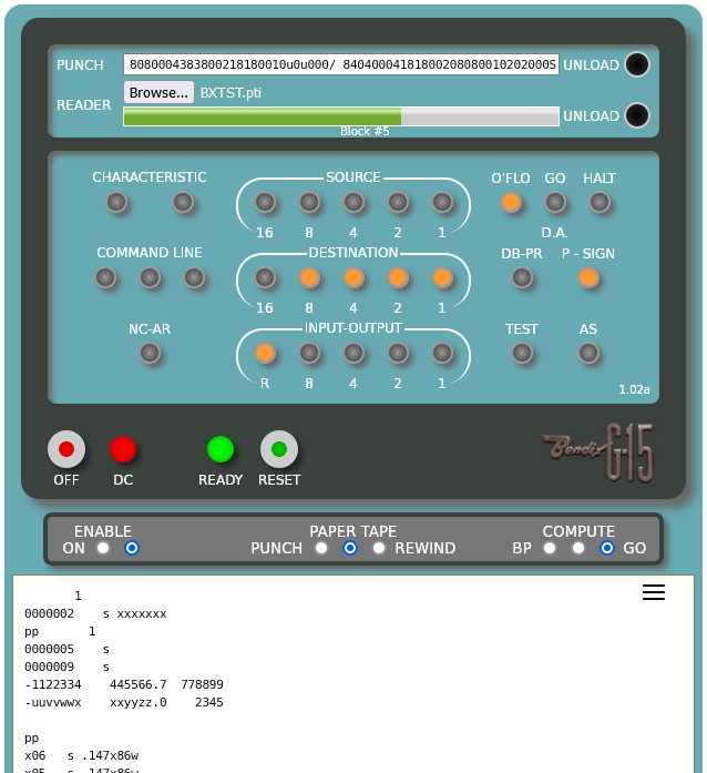
In the top section of this panel, the paper tape punch is represented by a text box showing the most recent data output by the punch. The paper tape reader is represented by a standard file picker control for selecting tape image files and a progress bar showing how much of the current tape image (if any) is yet to be read.
In the middle section, the neon lamps are represented faithfully, except that the AS lamp has been repositioned from below the INPUT-OUTPUT lamps so that it is next to the TEST lamp.
The third section of the panel contains a few buttons and lamps used to initialize and terminate the emulator.
Immediately below the panel proper is an area representing the toggle switches that were on the base of the system's electric typewriter. These are implemented as radio buttons. You can click either the buttons themselves or their captions to change the state of a switch.
The white area below the switches represents the "paper" of the electric typewriter.
Each of these items is discussed in more detail below.
On a real G-15, the paper tape punch was located within the system cabinet behind the paper tape reader. Punched tape came out through a slot just above the reader and fell to the floor. There was no take-up reel. A switch allowed you to run out the tape so that it could be torn off after punching.
In the emulator, punched tape is represented by a text box next to the PUNCH caption. This box shows the most recent output of the punch, which scrolls to the left as it is generated.
The punch operates at 17.2 characters per second, one character every two drum cycles. The capacity of the punch output buffer is about 262,000 characters, which represents about four hours of continuous punching. Once this limit is reached, further punch output is discarded by the emulator until the buffer is cleared.
To "tear off" the tape and access the punched data, click the UNLOAD button to the right of the text box. This will open a small panel on top of that button with additional options to control the punch buffer:
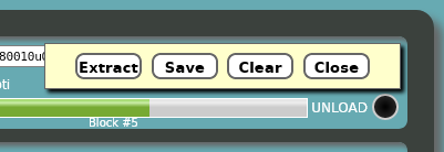
Extract – Opens a temporary window and copies the contents of the punch output buffer to that window. From that temporary window you can save the contents of the window to a file or copy/paste the data into another program. If you save directly the window, make sure you save as text, not HTML. When you are finished, simply close the temporary window.
Save – Opens a standard save-file dialog to save the buffer contents as a text file on your local system. The dialog provides a default name, which you can change before saving. If your browser saves the file without opening a dialog, check your browser settings – there should be an option to select how downloads are to be saved.
Clear – Clears the punch buffer and closes the panel.
Close – Simply closes the panel.
Paper tape images are ordinary ASCII text files. A basic G-15 system supported only hexadecimal input and output, using digits 0-9 and letters u-z (instead of the more common 0-9 and a-f convention). The paper tape devices used a five-bit code, as follows:
-
If the fifth bit is a 1 (representing a hole in the tape), the tape frame is a data digit and the other four bits indicate the hexadecimal value of that digit, 0-9 and u-z.
-
If the fifth bit is zero, then the fourth bit is ignored, and the remaining three bits represent a binary control or punctuation code, thus:
-
0_000= 0: " -
0_001= 1: "-" – Minus sign -
0_010= 2: "C" – Carriage return -
0_011= 3: "T" – Tabulate -
0_100= 4: "S" – Stop (end of block, halts the reader) -
0_101= 5: "/" – Reload (copies four words from line 23 to line 19) -
0_110= 6: "." – Period (used for decimal points) -
0_111= 7: "H" – Wait (on input, this is treated the same as data digit "0"; on output, it indicates a digit in memory was intentionally skipped by the punch formatting codes).
-
-
Although the G-15 ignored the fourth bit in a tape frame when the fifth bit was zero, the following letter codes can be used to represent such tape frames. Apparently this was of some use in equipment with which the G-15 would exchange tapes. These codes are not output by the G-15 paper tape punch:
-
01000: "I" equivalent to " -
01001: "J" equivalent to "-", Minus sign -
01010: "K" equivalent to "C", Carriage return -
01011: "L" equivalent to "T", Tabulate -
01100: "M" equivalent to "S", Stop -
01101: "N" equivalent to "/", Reload -
01110: "O" equivalent to ".", Period -
01111: "P" equivalent to "H", Wait
-
The characters in quotes above are the codes used by the emulated punch on output and recognized by the emulated reader on input. The punch outputs hexadecimal u-z in lower case and control codes in upper case, but the reader recognizes all letter codes in a case-insensitive manner.
To allow identification and descriptive information to be included in the file, comments may be included by prefixing them with a "#" character. A comment may start at any point in the file, including in the middle of data and control digits. The comment is terminated by the next ASCII carriage return (hex 0D) or line feed (hex 0A) encountered.
Any comments, or any characters in the file other than those specified above, are simply ignored by the reader and do not materially affect the speed with which the file will be read. The punch will output an ASCII new-line sequence after each "/" or "S" code, which will then be ignored by the reader on input.
See the G-15 Paper Tape Format document for more information on the construction of paper tape data.
Attempting to read from the paper tape reader with an empty input buffer or no tape image loaded causes the I/O operation to hang. The I/O can be manually canceled by keying ENABLE+S on the typewriter. See the Typewriter Switch Panel section below on the ENABLE switch and its use.
You can load multiple tape image files into the reader. They will be concatenated in the reader's buffer in the order loaded and will behave as one long tape image. Note, however, that if you select multiple files at once in the file picker control, the order in which the files are loaded into the buffer is operating system and browser dependent. If you need to control the order of the image data in the buffer, select the files one at a time with separate invocations of the file picker.
The progress meter shows how much unread data is still in the buffer. The meter bar will be all the way to the right after an image file is loaded and will shrink to the left as the data is read, proportionate to the amount of data left in the buffer.
The reader operates at a speed of 250 characters (tape frames) per second. The capacity of the reader's buffer is limited only by the amount of memory the browser is willing to allocate for it – probably at least several megabytes.
The middle section of the panel has neon lamps showing a portion of the internal state of the system:
-
CHARACTERISTIC – The "characteristic" bits from the current command word.
-
COMMAND LINE – The contents of the CD register, indicating which drum line is currently supplying command words. Binary values 000-101 (0-5) indicate lines 0-5, 110 (6) indicates line 19, and 111 (7) indicates line 23.
-
NC-AR – The state of the CG flip-flop. If lit, the next command will be taken from the AR (accumulator) register rather than the current command line on the drum.
-
SOURCE – The source field from the current command word.
-
DESTINATION – The destination field from the current command word.
-
INPUT-OUTPUT – Indicates the current input/output operation in progress. If the R ("Ready") lamp is lit, no I/O is in progress and the I/O subsystem is ready to accept a new command. Otherwise the remaining four bits indicate the device to which the current I/O operation is addressed. See the G-15 Operating Manual, page 19, for a list of the I/O device codes.
-
O'FLO – Indicates the state of the FO flip-flop, which is set when an arithmetic overflow condition has been detected. The flip-flop is reset when a Test for Overflow command is executed.
-
GO D.A. – If lit, the Differential Analyzer accessory is in operation (the retro-g15 emulator does not support this device).
-
HALT – If lit, the processor is in a stopped condition, either because it has not yet been started, has been stopped manually using the COMPUTE switch, has been stopped programmatically by a Halt command, or the processor has been single-stepped. To start the processor, change the COMPUTE switch to the middle (off) position, then to either the GO or BP position.
-
DB-PR – If lit, the current command word has the S/D (double-precision) bit set. This usually indicates the processor will operate on two words at a time.
-
P-SIGN – Indicates the state of the IP flip-flop, which carries the sign bit used for multiplication and division in the two-word registers (PN, ID, MQ).
-
TEST – Indicates the state of the CQ flip-flop, which holds the result of a test command. When this lamp is lit, the result of the prior test command was "true" and the next instruction will be taken from a memory location one word after it otherwise would.
-
AS – Indicates the state of the AS flip-flop. If lit, the input buffer (line 23) will be automatically reloaded when full without the need for a Reload code in the data. This feature is part of the optional Alphanumeric (AN) accessory. The AN is not currently supported by the emulator, but its automatic reload functionality is.
The number in the lower-right corner of this section of the Control Panel indicates the version of the retro-g15 emulator you are running.
At the bottom of the Control Panel on the left are two buttons and two lights. These emulate similar buttons and lights on a real G-15 panel.
When you initialize the emulator by clicking the Start the Emulator button on the home page, the Control Panel will overlay the home page. The DC and READY lamps will not be lit. This emulates the state of a real system after AC power had been turned on but before the DC power supplies had been energized.
To "power up" the emulator, click the green RESET button. On a real system, you had to hold this button down for a few seconds until the red DC lamp illuminated, indicating that the DC power supplies had reached their operating levels. In the emulator, a simple click of the RESET button is all that is required, and the red lamp turns on after a short delay.
At that point the emulator, like a real G-15, expects a tape image to have been loaded into the paper tape reader, and that the first block on that image is the data for the system's Number Track, which provided timing and control signals to the hardware. The emulator does not use the Number Track, but a program can read its contents and make use of the data, so that data should be loaded at power-up.
As a convenience, the emulator automatically preloads the paper tape reader's input buffer with the tape image for the PPR (Program Preparation Routine) utility. Simply pressing RESET after initialization will load from that tape image the Number Track and the second block, which is the PPR loader.
If you want to load a different bootable tape image than PPR, then before clicking RESET, click the reader's UNLOAD button, select a file with the desired tape image, and then click RESET. Once the first two blocks of the initial tape image have been loaded, the green READY light illuminates and the emulator is ready for use. Click the GO radio button for the COMPUTE switch to start the tape's program.
If you want to load a non-bootable tape for a program (i.e., one that does not have the Number Track data as its first block):
- Leave the default PPR tape image in the reader's buffer and click RESET.
- Once the first two blocks have been read from that image and the green READY light illuminates, click the UNLOAD button for the reader.
- Load the tape image for the program you want to run.
- Load the first block of the new image by entering ENABLE+P on your keyboard.
- Click the GO radio button for the COMPUTE switch to start the tape's program.
If you click RESET without a tape image loaded into the paper tape reader, the system reset mechanism will succeed, the green READY light will illuminate, and the emulator will be usable, but the paper tape reader will be left in a hung condition and the Number Track will contain all zero bits. To reset the hung reader, key ENABLE+S on the typewriter, which cancels the read operation.
The RESET button can be clicked at any time the processor is in a halted state. This will restart the system-reset process, and if a tape image is currently loaded, read the next two blocks from it.
The OFF button "powers off" (shuts down) the emulator. Double-clicking it stops the processor, cancels any input/output operation in progress, and returns to the emulator home page. Any buffered output for the paper tape punch and typewriter is lost, so be sure to save anything you want to keep before double-clicking this button.
Below the Control Panel are three sets of radio buttons that represent three toggle switches on the front of the base of the G-15 electric typewriter.
The ENABLE switch (also known as the "safety" switch) controls whether certain keyboard keys send commands to the G-15 hardware. The G-15 did not have an operating system to interpret keystrokes. Instead, the A, B, C, F, I, M, P, Q, R, S, T, 0, 1, 2, 3, 4, 5, 6, 7, /, -, TAB, and RETURN keys on the typewriter keyboard were hardwired directly into the G-15 logic circuits and operated as if they were push-buttons on a control panel. The signals from these keys were gated by the ENABLE switch, however, so that if that switch was in the right-hand (off) position, the system ignored such keystrokes.
For example, ENABLE+S causes any current input/output operation to be canceled. ENABLE+A causes the contents of the AR register to be typed out. See the G-15 Operating Manual, section "CONTROL KEYS (With Enable Switch ON)," starting on page 22, for a list of all the keyboard commands and their functions.
The switch can be turned on by clicking either its left-hand radio button or its ON caption. It can be turned off by clicking either its right-hand radio button or the ENABLE caption. The switch in its "on" state also suspends typewriter output until it is turned off again. The suspended output is not lost, just delayed until the switch is turned off.
With the retro-g15 emulator running in a browser window, it is somewhat inconvenient to turn the switch on, type one or more keys, then turn the switch off, so the emulator provides a convenient shortcut. The keyboard ESC key can be used like a shift key. When the ESC key is pressed, the ENABLE switch turns on; when the ESC key is released, the switch turns off. Thus, you can simply press and hold the ESC key along with one or more of the other keys listed above to enter control commands.
Note that the emulator will receive keystrokes from your workstation keyboard only when its window has the input focus, i.e., when that browser window or tab is the currently selected one on your display.
Also note that the 0-9, U-V, S, -, /, TAB, and RETURN keys are also used during data entry into the system. These keys are effective when the ENABLE switch is in the off position and the INPUT-OUTPUT lamps on the Control Panel have the configuration 01100 (a Type-In command). See the section on Typewriter Input and Output below for information on using the typewriter for data input.
The PAPER TAPE switch is normally left in its middle (off) position. When the switch is changed to its PUNCH position, any output to the typewriter is automatically copied to the paper tape punch. When in this mode, the punch operates at the same speed as the typewriter, about eight characters/second. The switch can enable or disable this mode at any time, even while output to the typewriter is in progress.
When the switch is changed to its REWIND position, any tape image loaded in the paper tape reader is rewound to its beginning. The switch may be changed back as soon as the rewind initiates. The rewind operation will continue and stop automatically when the beginning of the image is reached.
The switch setting can be changed by either clicking one of the radio buttons or a button's corresponding caption. Clicking the PAPER TAPE caption sets the switch to its middle (off) position.
The COMPUTE switch controls the operating state of the processor. In its center (off) position, the processor is halted. Changing the switch to this position will halt the processor at the end of the currently executing command. Any input/output operation currently in progress will continue until it is completed, however.
Changing the switch to the GO position will start the processor at the next command to be executed, as determined by the N field of the prior instruction or the effect of the ENABLE+F and ENABLE+C keyboard control commands.
Changing the switch to the BP position will start the processor as for GO, but programmed breakpoints will be enabled. If a command is executed with its BP bit set, the processor will halt after that command has been read from memory but before it is executed. The HALT lamp on the Control Panel will light. You can distinguish a halt due to a Halt command from one due to a breakpoint by examining the lamps in the SOURCE and DESTINATION registers – if the source is 10000 (16) and the destination is 11111 (31), the halt was due to a Halt command – otherwise it was due to a breakpoint stop or manually changing the COMPUTE switch to its off position.
When the processor is halted, it can be restarted by changing the COMPUTE switch to the middle (off) position and then to either the GO or BP position.
The typewriter device used with the G-15 was a modified IBM Model B electric typewriter. Various carriage widths were available, ranging from 80 to 132 columns.
The white area below the Control Panel represents the "paper" of the typewriter. The emulator models a 132-column carriage. The width of the paper area will adjust to the width of the browser window, but will not increase beyond the width necessary to display a 132-character line. If the paper area is too narrow to show the full length of the printed text, it will scroll horizontally.
The typewriter operates at a speed of 8.6 characters per second, one character every four drum cycles. Tab stops are hardwired at every five columns (6, 11, 16, 21, ... 131). The capacity of the typewriter's output buffer is 10,000 lines, which typically provides several hours of printing. When this limit is exceeded, the oldest lines are discarded.
When the emulator's browser window has the input focus (i.e., it is the currently selected window or tab on your desktop), keystrokes on your workstation keyboard will be echoed on the "paper," but unless the ENABLE switch is on or a program has initiated a command for typewriter input, these keystrokes will be ignored by the emulator. See ENABLE Switch above for information on its use with the keyboard.
When a program has executed a Type In input/output command, the INPUT-OUTPUT lamps on the Control Panel will have the configuration 01100. If the ENABLE switch is off, keystrokes on your workstation keyboard will be accepted for data entry. Only the 0-9, U-Z, -, /, S, TAB, and RETURN keys will be recognized in this mode. When typing letters, upper- and lower-case are considered equivalent. Note that while the period (.) character can be generated on output, that key is ignored on input.
Entering data into the system using the typewriter keyboard requires specific actions on your part to manage the buffering of the data on the drum and to terminate the input/output operation. See the G-15 Operating Manual, sections "CONTROL KEYS (with Enable Switch Off)" and "DATA INPUT KEYS," both starting on page 24, for information on using the typewriter keyboard for data entry.
All typed characters will be echoed to the paper, regardless whether they are recognized by the system or not. The backspace key is ignored, however. If the typewriter is not otherwise in use, you can type notes on it and use the RETURN key to insert vertical spacing between lines of output.
To save the contents of the typewriter paper, click the three-bar ("hamburger") menu icon in the upper-right of the paper area. This will open a small panel on top of that icon with additional options to control the typewriter output buffer:
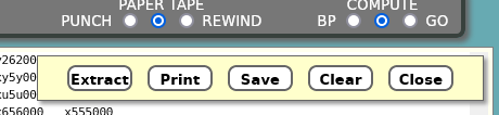
Extract – Opens a temporary window and copies the contents of the typewriter output buffer to that window. From that temporary window you can save the contents of the window to a file or copy/paste the data into another program. If you save directly from the window, make sure you save as text, not HTML. When you are finished, simply close the temporary window.
Print – Opens a standard print dialog to print the contents of the buffer to a local device. Most modern browsers also have an option to print to a PDF file.
Save – Opens a standard save-file dialog to save the buffer contents as a text file on your local system. The dialog provides a default name, which you can change before saving. If your browser saves the file without opening a dialog, check your browser settings – there should be an option to select how downloads are to be saved.
Clear – Clears the typewriter output buffer and closes the panel.
Close – Simply closes the panel.
Finally, note that since the basic G-15 was capable only of hexadecimal input and output, the typewriter cannot be used by G-15 software for general alphanumeric text input and output. The optional AN alphanumeric accessory mentioned above was capable of handling full alphanumeric text. One variant of this accessory, the ANC-1 (which the emulator does not presently support), allowed the typewriter to accept and print full alphanumeric text under program control.
At the bottom-right of the Control Panel is a G-15 logo. Double-clicking this logo will open the emulator's Diagnostic Panel in a separate window.
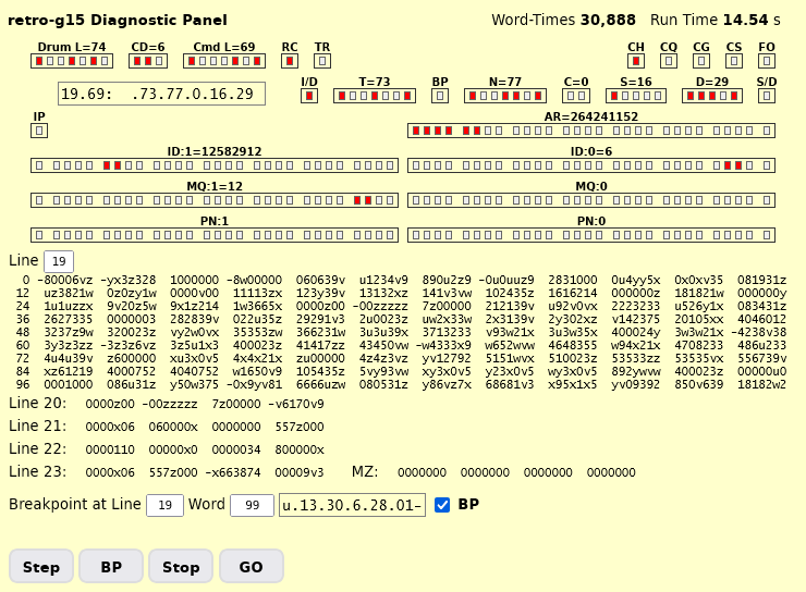
This panel is a retro-g15 emulator-specific addition. It is intended primarily as a monitoring and debugging tool for the emulator, but it can be interesting to view during normal operations. It shows the following:
- Current drum location
- Current command location
- Several significant flip-flops
- The fields of the current command word, both as PPR-like format and as bit registers
- The AR and two-word registers
- A single 108-word (long) drum line, selected using the Line text box
- The four-word (fast) drum lines
- A breakpoint insertion tool
The red lamps show individual bits in the registers, while the register captions show the decimal value of those registers.
In the upper-right of the window are two representations of the run-time clock, one stated in drum word-times and one in seconds. The clock is initialized when the emulator is loaded and runs whenever the processor is running.
Below the display of the four-word lines is a breakpoint insertion tool. Entering a drum line (or track) number and a word position in their respective text boxes will load that word from the drum memory into the field following the Word box and display the word in a PPR-like format. If the breakpoint (BP) bit in the word is set, the BP check box will be ticked. Only lines 0-23 can be accessed using this tool.
By ticking and unticking the BP check box, you can change the breakpoint bit in the corresponding word on the drum. Changing the state of the check box changes the word in drum memory immediately.
You can use this tool simply to examine words on drum lines and dissasemble them in PPR format. This doesn't affect anything on the drum unless you toggle the BP check box.
At the bottom of the window are buttons that can be used to start, stop, and single-step the processor.
You can open, close, and re-open the Diagnostic Panel as often as desired. Double-clicking the OFF button on the Control Panel will automatically close the Diagnostic Panel window if it is open.
The emulator can generate a trace of instruction activity as instructions execute. The trace is written to the JavaScript Console log, which in most browsers is part of the Developer Tools facility.
To do a trace, open the Developer Tools and select the Console item. If the Tools display as a panel in your main browser window, you may want to undock the panel as a separate window.
Then on the emulator Control Panel, double-click the emulator version number to activate tracing. The version number is to the right of and below the AS lamp. The version number will turn yellow while tracing is activated. Double-click the version number again to deactivate tracing.
As instructions execute, each one will be written to the JavaScript console log as one or more lines. The first line will be an interpretation of the instruction in a PPR-like format. Subsequent lines will show the register or drum line activity during the instruction's Transfer state. For example:
<TRACE  6> 19.u7: u.04.04.0.22.02
              TR: 22:  0=    110  0>  2:  0=    110
              TR: 22:  1=     x0  0>  2:  1=     x0
              TR: 22:  2=     34  0>  2:  2=     34
              TR: 22:  3=800000x  0>  2:  3=800000x
-
<TRACE 6>says that this line was written when the paper tape reader was at or within block number 6 (0-relative) of the currently-mounted paper tape. -
19.u7is the location of the instruction (line 19, word u7=107) -
u.is termed the "prefix" and in this case indicates an "urgent" (immediate-mode) instruction.w.indicates a "wait" (deferred-mode) instruction. If there is nouorwprefix, then the instruction is in deferred mode, unless either the destination (D) field is 31 (special command) or the T (timing number) field is equal to the instruction word location on the line plus one word (i.e., T=L+1). These special cases are due to convenience optimizations that PPR performs when assembling an instruction and a prefix has not been specified. -
04.04.0.22.02represents the remaining fields of the instruction in T, N, CH, S, D order. The 4-bit of the CH field represents the single/double-precision indicator in the low-order (sign) bit of the word. The two low-order bits of the word indicate the characteristic for the instruction. [Welcome to the coding conventions of 1950s programming.]
Below the instruction line, the trace shows any register or drum-line activity that took place during the instruction's Transfer state. The first item indicates the type of transfer or type of data:
-
TR– ordinary transfer -
AR– transfer to AR (no addition) -
AR+– transfer to AR (with addition) -
VA– transfer via AR (CH=2, word precession) -
ID– transfer to Multiplicand/Denominator register -
MQ– transfer to Multiplier/Quotient register -
PN– transfer to Product/Numerator register -
REG– transfers involving arithmetic registers (1- and 2-word) -
<Div>– transfer during Divide instructions -
RET– transfer during Return Exit instructions -
MRK– transfer during Mark Exit instructions
A notation such as n> where n is 0-3 indicates the characteristic transformation that takes place during transfer:
- 0 = TR: no transformation
- 1 = AD: convert to/from 2-s complemenent representation
- 2 = TVA: Transfer via AR (for sources and destinations 0-27) or AV: Transfer Absolute Value (for sources and destinations 28-31)
- 3 = AVA: Add via AR (for sources and destinations 0-27) or SU: Substract (for sources and destination 28-31)
FO is the state of the overflow flip-flop after the instruction executes. A * suffix indicates overflow occurred during this operation.
The G-15 has a very unusual architecture, heavily influenced by the NPL Pilot Ace, and uses a source-to-destination command model rather than the more common operation-code/operand-address model. Because of this, the command words have a lot of configurations for which the behavior is not specified in the documentation, although they could probably be deduced with some, perhaps significant, effort from the logic diagrams. This sort of thing is very difficult to deal with in an emulator like retro-g15, which operates more or less at a word level, not a bit level.
The user documentation for the system describes what might be referred to as "standard commands" for which the behavior was reasonably well defined. When programmers departed from those standard patterns (and in the 1950s, programmers did whatever they could get away with to optimize their code), that may have resulted in predictable behavior at the time, but that specific behavior is quite difficult to determine with the information we have available 70 years later.
When the emulator recognizes such a situation, an entry that identifies the command being executed is written to the emulator's JavaScript console log. This log can be inspected using the browser's Developer Tools facility.
This standard-usage violation detection mechanism is a work in progress and is intended to assist in improving the emulator's support of G-15 software over time. It is likely not accurate in all cases and should not be relied upon.