After some use it was clear that pressing the rotary encoder was a PITA so with some free time in the horizont a new add-on printable structure with capacity to hold two new buttons was designed and added to the scratchTJ structure.
Here is a new edited video of scrtachTJ in action:
Click to watch!!
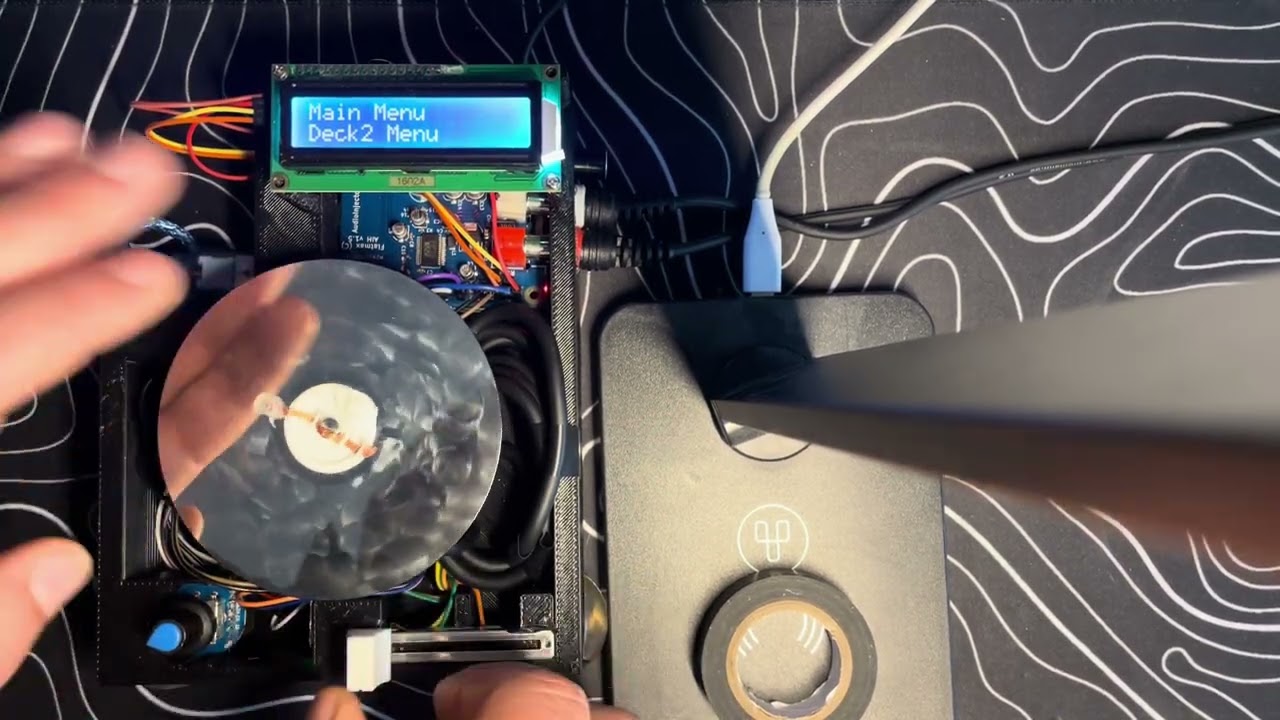
Those 2 buttons are for navigation purposes, enter and back. This makes navigating the menus friendlier.
Now the rotary encoder press and long press actions can be used for other purposes.
In latest commit, now holding the rotary encoder long press enters Pitch Mode, which allows setting the deck playback speed.

- Buttons extender: Tinkercad Model
The journey of creating a DIY digital turntable began with a spark of inspiration from two YouTube videos: SC500 DIY CDJ build and SC1000 Open Source Turntable. If you're interested in buying one, check out the SC1000 MK2 here. It’s honestly a fantastic piece of gear if you can get your hands on it. The innovative work by the_rasteri on these models captivated me, and the idea of building a custom digital turntable took root. The goal was clear: adapt the open-source code of the SC1000 to work on a Raspberry Pi 2 equipped with an AudioInjector audio hat, and create a functional, customizable digital turntable using readily available components. Let's dive into how this all came together.
But first: one demo video of the thing running: (Click to watch)

Discovering that the SC500 units were scarce and difficult to purchase, I turned my attention to the SC1000's open-source code. Diving into the codebase, I sought ways to initialize a 1602 LCD display and integrate it with xwax, an open-source digital vinyl emulation software.
The first step was to get the LCD screen operational and establish communication with the Raspberry Pi. I experimented with the 1602A LCD display, ensuring it could display text and respond to inputs. Concurrently, I began working with a rotary encoder to navigate menus and control parameters.

With some assistance from GPT-powered coding suggestions, I developed C code to handle rotary encoder events. This allowed for start/stop control of the decks and adjustment of various parameters displayed on the LCD screen.
To enhance the functionality, I sourced a magnetoelectric rotary encoder and a DJ fader from AliExpress. I also upgraded the LCD display to a 1602A with an integrated circuit (IC) to reduce the GPIO pin usage on the Raspberry Pi.


Realizing the need for additional processing capabilities to handle the fader and the rotary encoder, I incorporated an Arduino Nano into the setup. The Arduino reads the input from these components and communicates with the Raspberry Pi via serial connection (TX/RX).
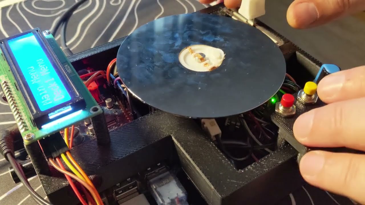
To emulate the feel of a real turntable, I wanted to incorporate capacitive touch sensitivity. Initial attempts using electric paint on a CD proved inadequate. The solution was to use an open hard drive (HDD) platter connected to the magnetoelectric rotary encoder. The platter, connected to the Arduino Nano acting as a capacitive sensor, provided the desired touch sensitivity.


- Raspberry Pi 2
- AudioInjector Sound Card
- 1602A LCD Display with IC
- Rotary Encoder with Push Button
- Arduino Nano (connected via TX/RX serial)
- 1200Ω Resistor
- DJ Fader
- Magnetoelectric Rotary Encoder
- Hard Drive Platter


To house the components and provide a user-friendly interface, I designed custom parts in Tinkercad:
- HDD Adapter: Tinkercad Model The HDD adapter features channels for a 1.5mm wire to connect the platter to the shaft, enabling touch sensitivity.
- Enclosure: Tinkercad Model The enclosure was designed to accommodate all components, though initial prints required adjustments to fit the Raspberry Pi properly.
Analyzing the SC1000 source code, I identified areas to integrate the new hardware components. Modifications included:
- Initializing the 1602A LCD display.
- Handling input from the Arduino Nano for the fader and rotary encoder.
- Implementing capacitive touch functionality for the platter.
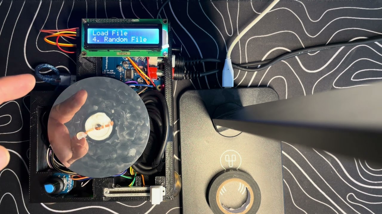
- Extending menu options to adjust fader settings, platter speed, pitch factor, and more in real-time.
](https://youtu.be/jpz3jol8UZQ) (Click to watch)
The system was expanded to:
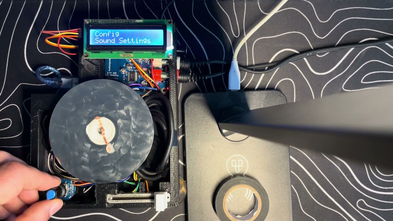
- Control ALSA mixer parameters for the sound card.
- Enable recording from the sound card inputs.
- Provide adjustable fader settings (cut curve, cut position switch).
(Click to watch)
If you're interested in making your own ScratchTJ or have ideas to improve it, I'd love to hear from you. The project isn’t perfect, and there are still so many ways to make it better, but that’s the beauty of open-source projects: it’s all about iteration and collaboration. I know there is a lot of stuff left behind to fully write a DIY guide, so
Kiitos paljon ja happy scratching!