Sensor Approximation
Since the Cubesat's dynamics simulation is required to represent the real circumstances as precise as possible, also the characteristics of various onboard-instruments need to be taken into account when it comes to attitude determination.
To imitate the sensor readings in space, the "exact" simulated ambient values(e.g. heading, location..) will be manipulated with different phenomena like noise or an offset-value. For the reason that all components of the Cubesat will be operating in a very confined space, microelectromechanical ("MEMS") sensors must often be used as a replacement for state of the art instruments. As a consequence, an examination of the different distortion phenomena is essential for the mission's success.
The following instruments will be examined:
- A Gyroscope (MEMS)
- A magnetic field sensor (MEMS magnetometer)
- Horizon detector
- Star detector
To eventually legitimate the sensor-simulations, real measurements of selected instruments will be acquired and compared with the simulated results.
The main signal-distorting phenomena affecting most sensors are:
- An unknown offset (often affected by temperature)
- Nonlinearity (often affected by temperature)
- Noise
- Maximum output value range
- Quantization (due to digital data transmission)
Generally, a gyroscope is capable of measuring angular velocities.
While there exists a whole bunch of different working principles, like for example Ring laser gyroscopes and Fiber optic gyroscopes, the use of anything but MEMS gyroscopes seems unreasonable due cost and the available space.
One of it's main disadvantages is the unknown offset. it might be quite small, but integrating the sensor output over time to retrieve absolute angles is not advisable due to the resulting integration error. A solution would be to retrieve the offset by calibration: First, collect n data samples at a known angular velocity. Then calculate the mean of the n data samples and subtract the known angular velocity. The result will be an approximation of the offset (if n converges against infinity, it will become more precise due to the lower impact of noise). However, an additional sensor(e.g. star sensor) must be available to measure the angular velocity during the calibration. In this case, a fusion of both sensor readings could potentially result in more accurate results.
To acquire a rough understanding of what we are dealing with, the popular MEMS gyroscope L3GD20H from ST Microelectronics will be analyzed.
Regarding to its datasheet, the following core parameters can be extracted:
- Measurement range: ±245, ±500 or ±2000 deg/s; We will choose ±500 deg/s for evaluation
- Offset: ±25 deg/s; We will choose 25 deg/s to simulate the most critical possibility
- Output resolution: 16 Bit -> Minimum step size: 2 * 500 deg/s / 2^16 = 0.0153 deg/s
- Rate noise density: 0.011 (deg/s) / sqrt(Hz) at a 50 Hz sample rate
Assuming that the noise is white noise, so that it has the same intensity at all possible frequencies(flat power spectral density), the root mean squared value of the noise is:
0.011 deg/s / sqrt(50 Hz) = 1.556 * 10^-3 deg/s^1.5
In order to calculate the variance of the noise, the result must be divided by the minimum output resolution and then squared[1]:
( 1.556 * 10^-3 deg/s^1.5 / 0.0153 deg/s )^2 = 0.0103
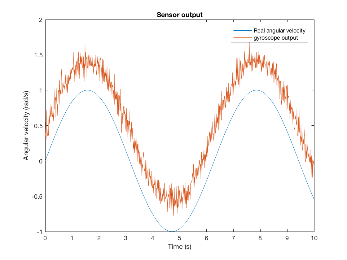
The noise and offset can quite clearly be seen, but the range-clipping and quantization distortions have little impact, observing with bare eyes.
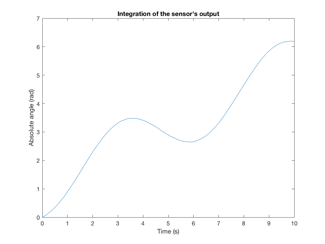
As it can be noticed in the second simulation result, the integration acts comparable to a low-pass filter, since it blocks the rather high frequency (compared to the actual signal) components of the noise.
Although the integrated sensor values should oscillate with a mean of zero, they do not do so because of the offset in the angular rate. After just 10s, the integrated error is already located at offset * time = 25 deg/s * 10s = 250 deg, which is about 4.363 radians.
A magnetic field sensor is basically a device that is able to characterize the ambient magnetic field's flux density described by a specific direction and magnitude. Whereas the direction can be given in any format, the magnitude is most commonly measured in the derived SI unit teslas.