-
Notifications
You must be signed in to change notification settings - Fork 0
XBEE Configuration
The MVP system design called for a pair of XBEE radios configured for AT mode with the first as a single Coordinator AT and the second as a Router AT. With this configuration the XBEE system allows the router to only talk to the coordinator while the coordinator may only talk to the router. It is a single point to point link as seen in the image below:
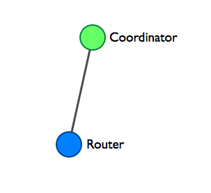
It is this basic system which I have implemented in ER2. I have a third XBEE radio also configured as a router, and depending on whether or not I can get the system configured to operate correctly in a star topology, will decide if I will demo it during the presentation on May 20th.
At the earliest opportunity I intend to spend time implementing a fully functional SerialParser system which will allow me to switch to XBEE API firmwares and thereby open up the mesh networking potential of the system. Likewise the firmwares for each node will need to be fleshed out and hardened for production use.
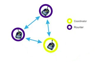
While it is possible to communicate with the XBEE radios directly over a serial connection, such as that provided by the USB breakout board as shown in the following image, it is a lot more user friendly to use the Digi Firmware Configuration Tool [xctu]. This tool is designed to work on the modern versions of the Microsoft Windows operating system.
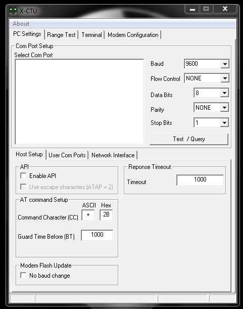
I followed the advice about configuring XBEE radio devices from many sources such as [configuring-xbee], [sensor-networks] and [xbee-pairing] I decided the way to configure the network for the initial system release would be adding all XBEE radios to the same PAN or Personal Area Network. While setting the Destination High and Destination Low of the RouterAT radios to 0 to ensure they are addressing the Coordinator on this PAN. The Coordinator is configured to speak to FFFF which is the broadcast address for the PAN.
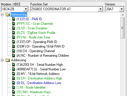
The image above shows the configuration page in the X-CTU utility. I set the following parameters shown in the table below for the single CoordinatorAT radio. The CoordinatorAT is responsible for maintaining order on the network, in my configuration I have configured it simply to allow this single radio to transmit broadcast data to all other radios on the network.
Parameter |
Value |
PAN ID |
1337 |
Destination High |
0 |
Destination Low |
FFFF |
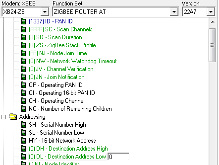
In the inital system I have two RouterAT radios configured to speak to the CoordinatorAT with the following settings in the table below.
Parameter |
Value |
PAN ID |
1337 |
Destination High |
0 |
Destination Low |
0 |
By configuring the mesh network in the this way has produced a system with the following topology, which details the Ardtweeno Gateway at the top, and two Ardtweeno Mesh Network Nodes on either side at the bottom:
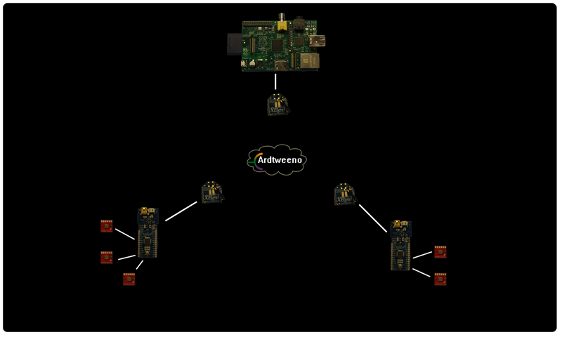
The PAN id is the number I chose for my personal Ardtweeno Mesh Network, however it is advisable you chose a value which better suits your needs. The settings used in the tables above are suitable for the initial Ardtweeno system, but with the change to the XBEE API firmwares in later versions, will require implementing a much more complex system for communicating between mesh network nodes. A fully featured and upgraded SerialParser system is the first step in achieving this goal as stated earlier in the document.