This project connects an esp32 to a VG400 central ventilation unit from Flexit, measures the temperatures of incoming and exiting air, and regulate the ventilation based on the readings of Radon, CO2, VOC, and humidity.
The project is still in progress. I blew a relay on the main board during this project and I suspect that the resistor for the relay controlling "high" fan speed might be too small.

- esp32
- SP425 controller board
- 3x3V [relays] (https://www.aliexpress.com/item/32963196636.html?spm=a2g0s.9042311.0.0.27424c4dnUIR03)
- 3x optocouplers
- Network cable (RJ45)
- [Prototyping board] (https://www.aliexpress.com/item/32944526042.html?spm=a2g0s.9042311.0.0.27424c4deBLnzu)
- 4x [Dallas thermometers] (https://www.aliexpress.com/item/32523899337.html?spm=a2g0s.9042311.0.0.27424c4d34b0Tb)
- 3x 1kOhm resistors
- 2x 2kOhm resistors
- 1x 4kOhm resistor
- Wires
- Smart-plug https://www.aliexpress.com/item/4000478798085.html?spm=a2g0s.9042311.0.0.27424c4dHoTBiU
- CO2, Radon, VOC, humidity sensor [Airthings Wave plus] https://www.airthings.com/en/wave-plus
- Intel nuc i5

- Home Assistant running in docker container
- Esphome running in docker container
- NodeRed running in docker container
This image is from the original project and is not absolutely correct. Follow the instructions below
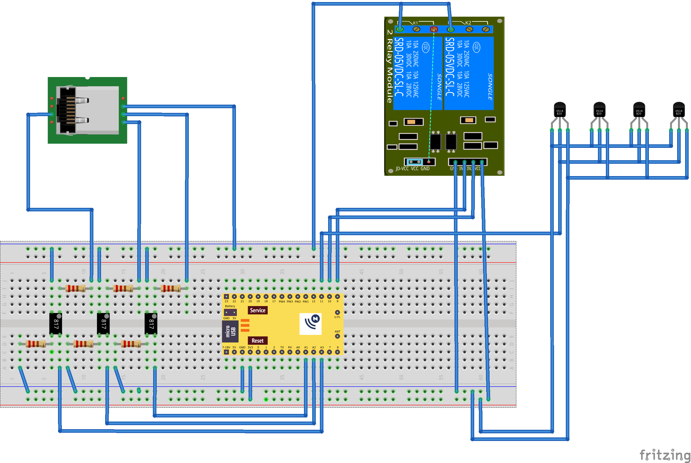
Connect the three 3 V relays to the ESP32:
- Pin 18: to relay 1 in
- Pin 19: to relay 2 in
- Pin 21: to relay 3 in
- ESP32 GND to relay GND-in
Connect the RJ45 wire to the protoboard. The pin numbers correspond to the pin numbers on the VG400 control board:
- wire pin 3: to a diode, and then to relay 3 out
- wire pin 3: with a 1 kΩ resistor to optocoupler 3 input
- wire pin 4: to relay 1,2,3 GND-out
- wire pin 5: to a 2.2 kΩ resistor, and then to relay 1 out
- wire pin 5: with a 1 kΩ resistor to optocoupler 1 input
- wire pin 6: to a 2.2 kΩ resistor, and then to relay 2 out
- wire pin 6: with a 1 kΩ resistor to optocoupler 2 input
- wire pin 7: to optocoupler 1,2,3 GND-in
Connect the three optocouplers to the ESP32
- Pin 32 to optocoupler 1 out
- Pin 33 to optocoupler 2 out
- Pin 26 to optocoupler 3 out
- optocoupler 1,2,3 GND-out: with 1 kΩ resistors to ESP23 GND
Connect the four DS18B20 temperature sensors to the ESP32:
- Pin 4 to DS18B20 data pin
- 4.7 kΩ pullup resistor for DS18B20 data pin
- 5V to DS18B20 5V pins
- ESP32 GND to DS18B20 GND pins
Connect power to the ESP32:
- Z-UNO, USB: power source
- Z-UNO, GND
Adjust and compile the esphome.yaml in and esphome instance. Download the binaries and flash it to the esp32 with a flashing tool. Subsequent flashing can then be performed Over The Air/network (OTA).