- Abstract
- Reference Circuit Diagram
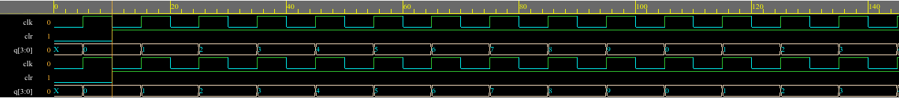
- Reference Waveform
- Circuit Details
- Truth Table
- Software Used
- Circuit Diagram in eSim
- Verilog Code
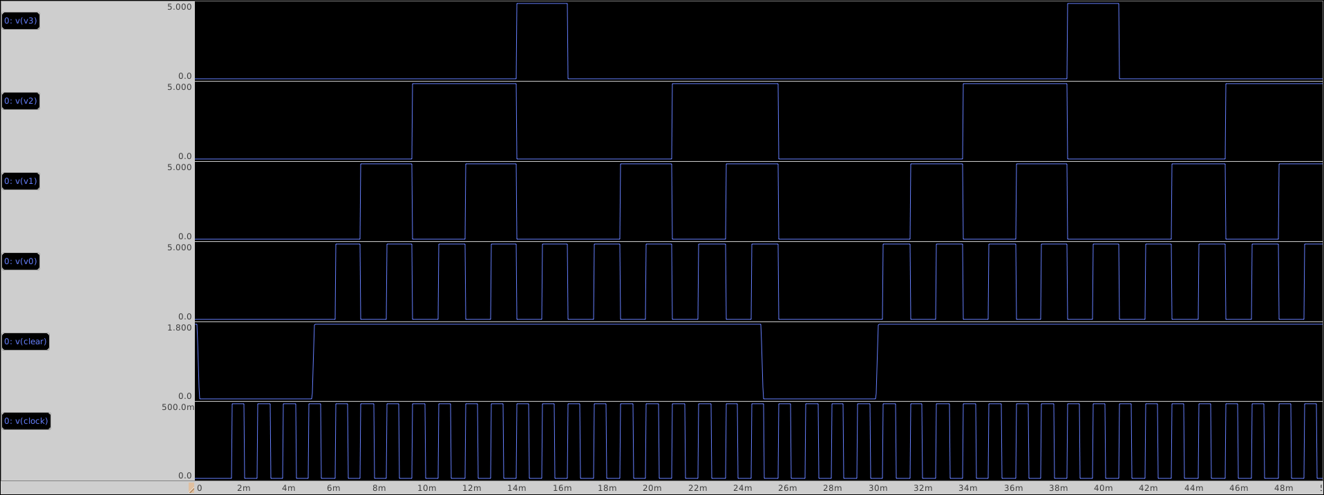
- Makerchip
- Makerchip Plots
- Netlists
- NgSpice Plots
- GAW Plot
- Steps to run generate NgVeri Model
- Steps to run this project
- Acknowlegdements
- References
Table of contents generated with markdown-toc
The MOD-10 synchronous counter has numerous applications such as digital clock, frequency divider, D2A, and so on. MOD-10 counters are also referred to as Decade counters or BCD counters. In this project, I used a JK flipflop as a counter and an astable multivibrator to generate the clock signal.

The waveform is simulated using EDA playground (https://www.edaplayground.com/)
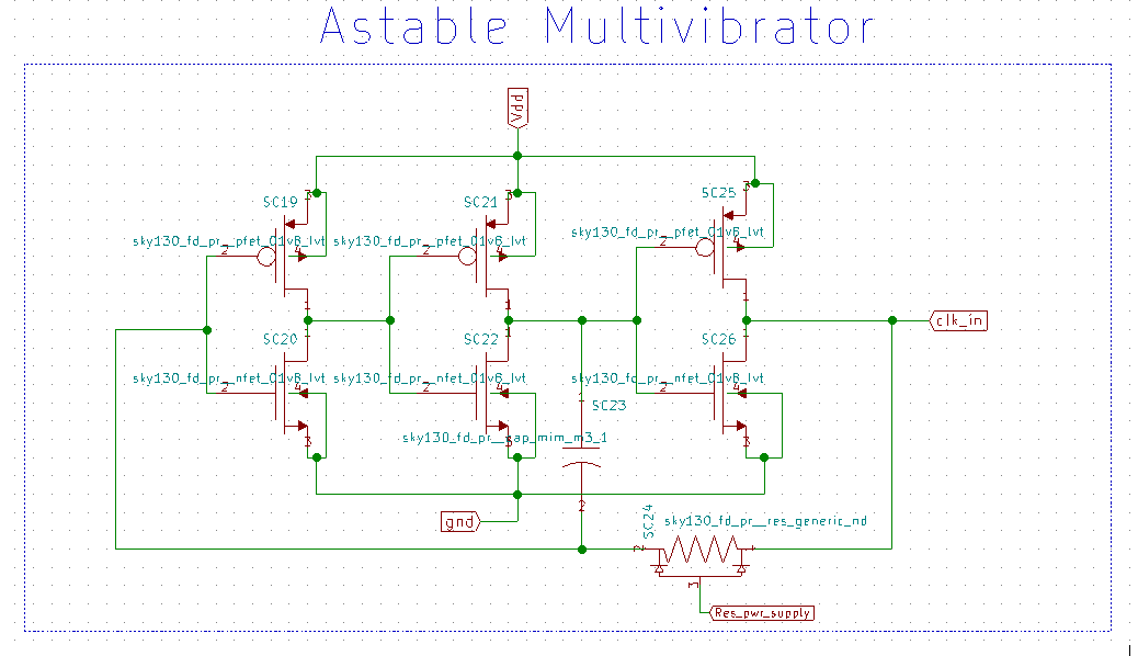
The MOD-10 synchronous counter has a count range of 0 to 9. Because the counter is synchronous, the clock signal is sent to all of the flip flops at the same time. The MOD-10 synchronous counter is built with both analogue and digital circuitry. The analogue circuitry consists of the astable multivibrator and the AND gate implemented in CMOS. The astable multivibrator is built by cascading three inverters and using a resistor and capacitor to generate a pulse signal for the clock. The inverters act as a buffer, and the direction of the capacitor's charging and discharging plays an important role in switching the inverter's inputs and outputs. The digital circuitry of MOD - 10 is made up of four JK flipflops with synchronous clear. The truth table is written and reduced using the K-map to obtain the boolean functions for the input and output to the flipflops. Using the Boolean function, the Verilog code for the digital circuit is written. Finally, the analog and digital circuits are integrated to form a mixed signal circuit.
The truth table along with the excitation table for each flipflop is shown below:
| Present State | Next State | J3 | K3 | J2 | K2 | J1 | K1 | J0 | K0 |
|---|---|---|---|---|---|---|---|---|---|
| q3 q2 q1 q0 | Q3 Q2 Q1 Q0 | ||||||||
| 0 0 0 0 | 0 0 0 1 | 0 | x | 0 | x | 0 | x | 1 | x |
| 0 0 0 1 | 0 0 1 0 | 0 | x | 0 | x | 1 | x | x | 1 |
| 0 0 1 0 | 0 0 1 1 | 0 | x | 0 | x | x | 0 | 1 | x |
| 0 0 1 1 | 0 1 0 0 | 0 | x | 1 | x | x | 1 | x | 1 |
| 0 1 0 0 | 0 1 0 1 | 0 | x | x | 0 | 0 | x | 1 | x |
| 0 1 0 1 | 0 1 1 0 | 0 | x | x | 0 | 1 | x | x | 1 |
| 0 1 1 0 | 0 1 1 1 | 0 | x | x | 0 | x | 0 | 1 | x |
| 0 1 1 1 | 1 0 0 0 | 1 | x | x | 1 | x | 1 | x | 1 |
| 1 0 0 0 | 1 0 0 1 | x | 0 | 0 | x | 0 | x | 1 | x |
| 1 0 0 1 | 0 0 0 0 | x | 1 | 0 | x | 0 | x | x | 1 |
| 1 0 1 0 | x x x x | x | x | x | x | x | x | x | x |
| 1 0 1 1 | x x x x | x | x | x | x | x | x | x | x |
| 1 1 0 0 | x x x x | x | x | x | x | x | x | x | x |
| 1 1 0 1 | x x x x | x | x | x | x | x | x | x | x |
| 1 1 1 0 | x x x x | x | x | x | x | x | x | x | x |
| 1 1 1 1 | x x x x | x | x | x | x | x | x | x | x |
J0 = K0 = 1
J1 = q3'q0 ; K1 = q0
J2 = K2 = q0q1
J3 = q0q1q2 ; K3 = q0
It is an Open Source EDA developed by FOSSEE, IIT Bombay. It is used for electronic circuit simulation. It is made by the combination of two software namely NgSpice and KiCAD.
For more details refer:
https://esim.fossee.in/home
It is an Open Source Software for Spice Simulations. For more details refer:
http://ngspice.sourceforge.net/docs.html
It is an Online Web Browser IDE for Verilog/System-verilog/TL-Verilog Simulation. Refer
https://www.makerchip.com/
It is a tool which converts Verilog code to C++ objects. Refer: https://www.veripool.org/verilator/
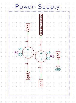
The following is the schematic in drawn in eSim:
Power Supply
Astable Multivibrator Circuit
Mixed Signal MOD-10 Synchronous Counter using JK Flipflop with Synchronous Clear

module jk_ff_sky130(j,k,clk,clr,q,qb);
	input clk,clr,j,k;
	output reg q;
	output qb;

	always @(posedge clk) begin
		if (~clr)
			q<=0;
		else begin
			case({j,k})
				2'b00 : q<=q;
				2'b01 : q<=0;
				2'b10 : q<=1;
				2'b11 : q<=~q;
			endcase
		end
	end
	assign qb = ~q;
endmodule
\TLV_version 1d: tl-x.org
\SV
/* verilator lint_off UNUSED*/  /* verilator lint_off DECLFILENAME*/  /* verilator lint_off BLKSEQ*/  /* verilator lint_off WIDTH*/  /* verilator lint_off SELRANGE*/  /* verilator lint_off PINCONNECTEMPTY*/  /* verilator lint_off DEFPARAM*/  /* verilator lint_off IMPLICIT*/  /* verilator lint_off COMBDLY*/  /* verilator lint_off SYNCASYNCNET*/  /* verilator lint_off UNOPTFLAT */  /* verilator lint_off UNSIGNED*/  /* verilator lint_off CASEINCOMPLETE*/  /* verilator lint_off UNDRIVEN*/  /* verilator lint_off VARHIDDEN*/  /* verilator lint_off CASEX*/  /* verilator lint_off CASEOVERLAP*/  /* verilator lint_off PINMISSING*/    /* verilator lint_off BLKANDNBLK*/  /* verilator lint_off MULTIDRIVEN*/    /* verilator lint_off WIDTHCONCAT*/  /* verilator lint_off ASSIGNDLY*/  /* verilator lint_off MODDUP*/  /* verilator lint_off STMTDLY*/  /* verilator lint_off LITENDIAN*/  /* verilator lint_off INITIALDLY*/

//Your Verilog/System Verilog Code Starts Here:
module jk_ff_sky130(j,k,clk,clr,q,qb);
	input clk,clr,j,k;
	output reg q;
	output qb;

	always @(posedge clk) begin
		if (~clr)
			q<=0;
		else begin
			case({j,k})
				2'b00 : q<=q;
				2'b01 : q<=0;
				2'b10 : q<=1;
				2'b11 : q<=~q;
			endcase
		end
	end
	assign qb = ~q;
endmodule


//Top Module Code Starts here:
	module top(input logic clk, input logic reset, input logic [31:0] cyc_cnt, output logic passed, output logic failed);
		logic  clr;//input
		logic  j;//input
		logic  k;//input
		logic  q;//output
		logic  qb;//output
//The $random() can be replaced if user wants to assign values
		assign clr = 1;
		assign j = $random();
		assign k = $random();
		jk_ff_sky130 jk_ff_sky130(.clk(clk), .clr(clr), .j(j), .k(k), .q(q), .qb(qb));

\TLV
//Add \TLV here if desired
\SV
endmodule
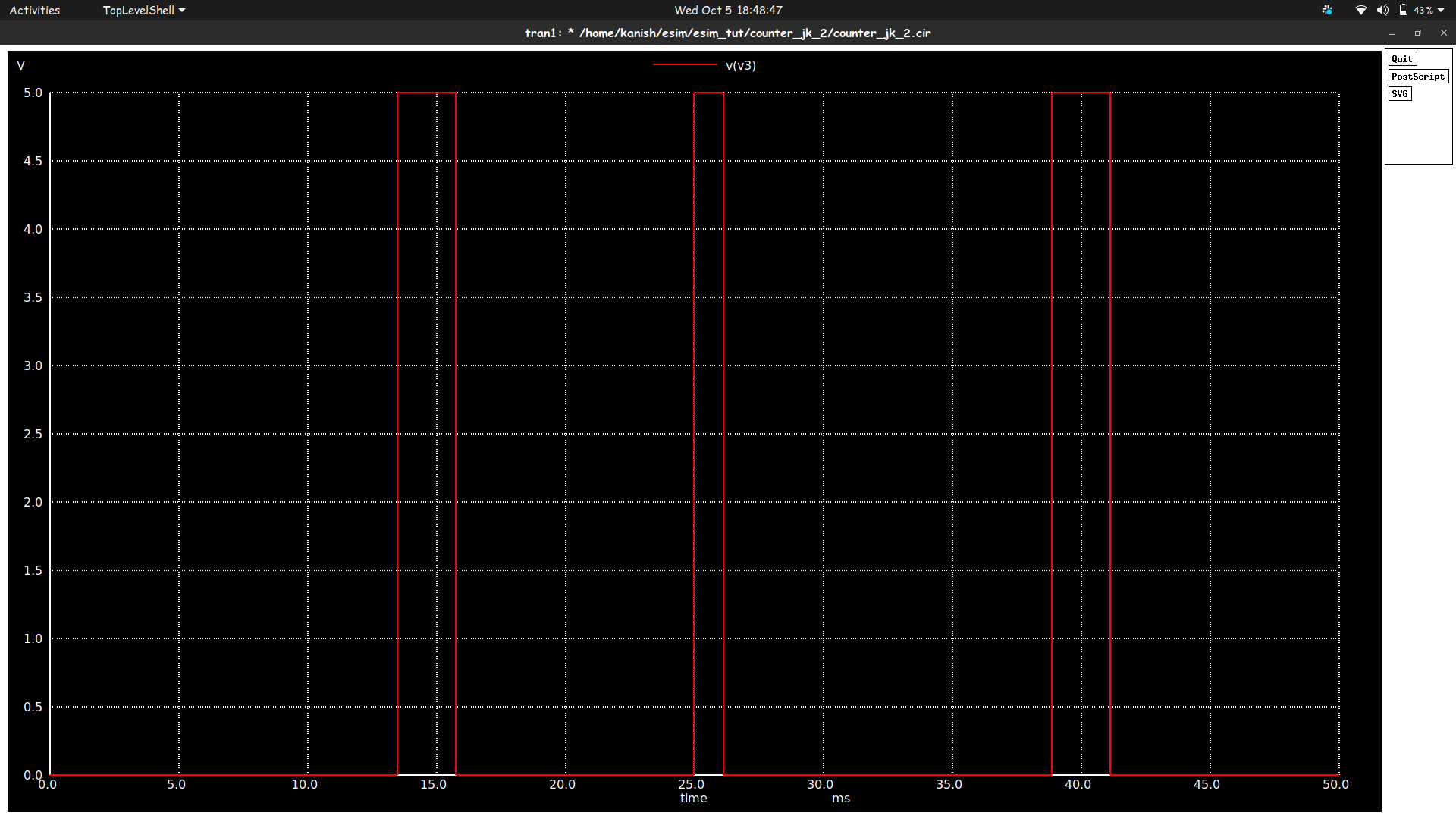
JK Flipflop Output
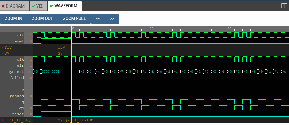
The plot here depicts the functionality of the positive edge triggered JK flipflop with synchronous clear for the inputs J = 1 and K = 1.
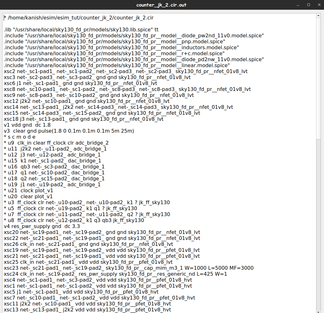
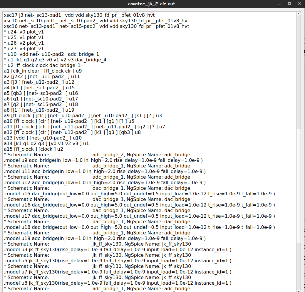
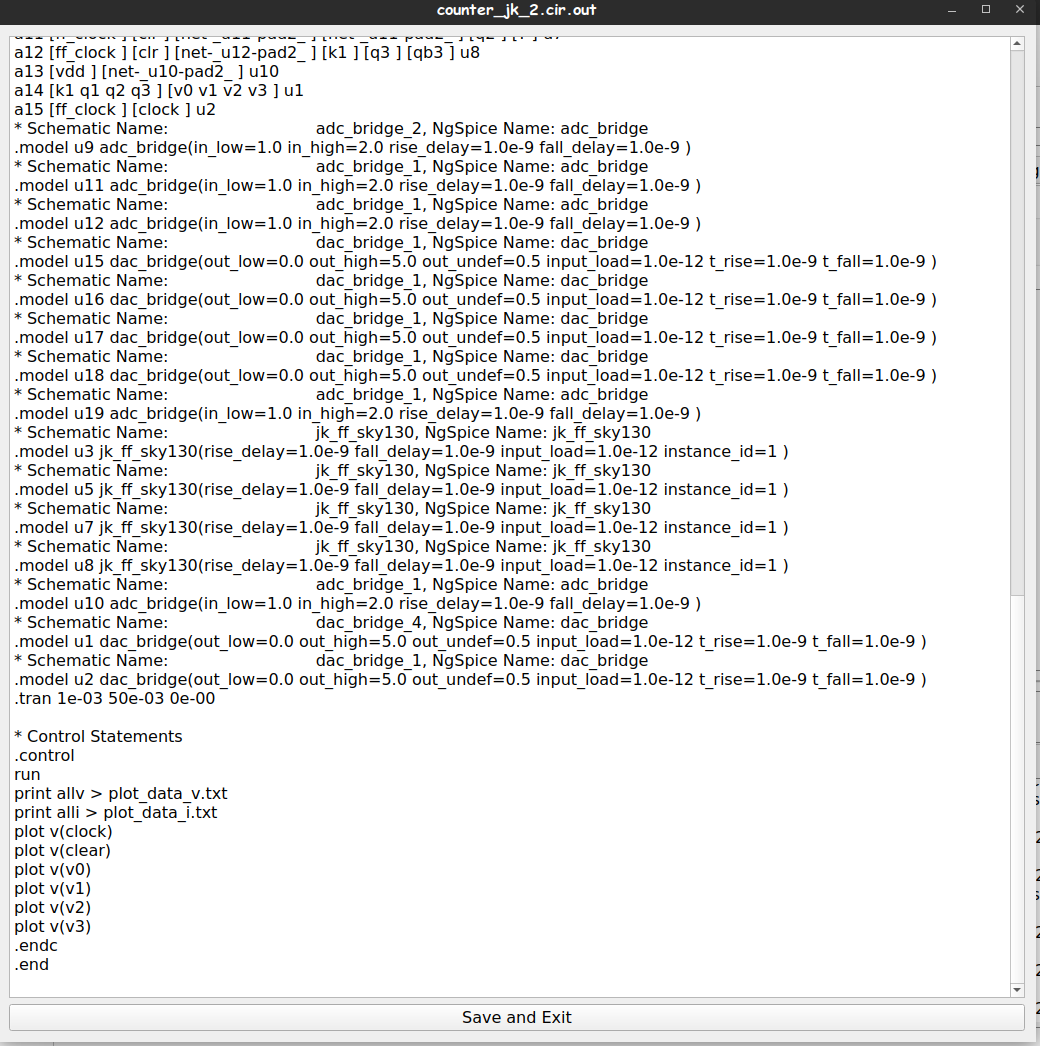
The following figures show the contents in the counter_jk_2.cir.out :
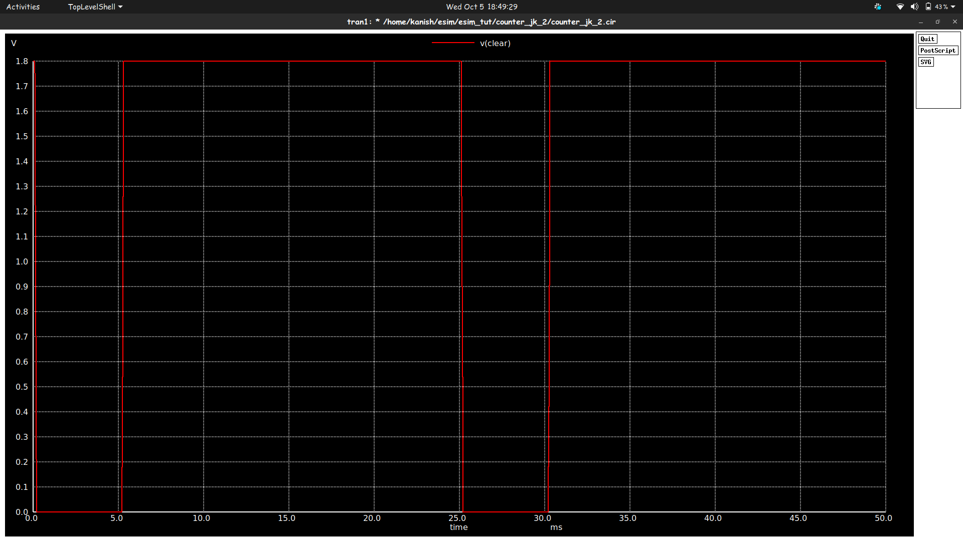
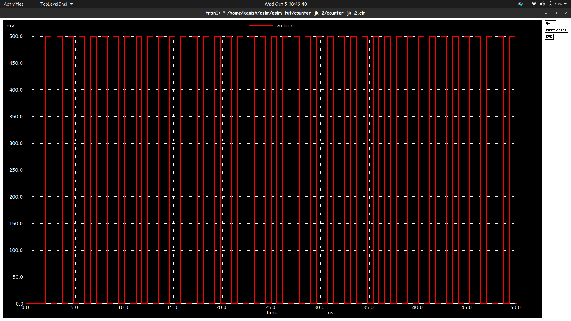
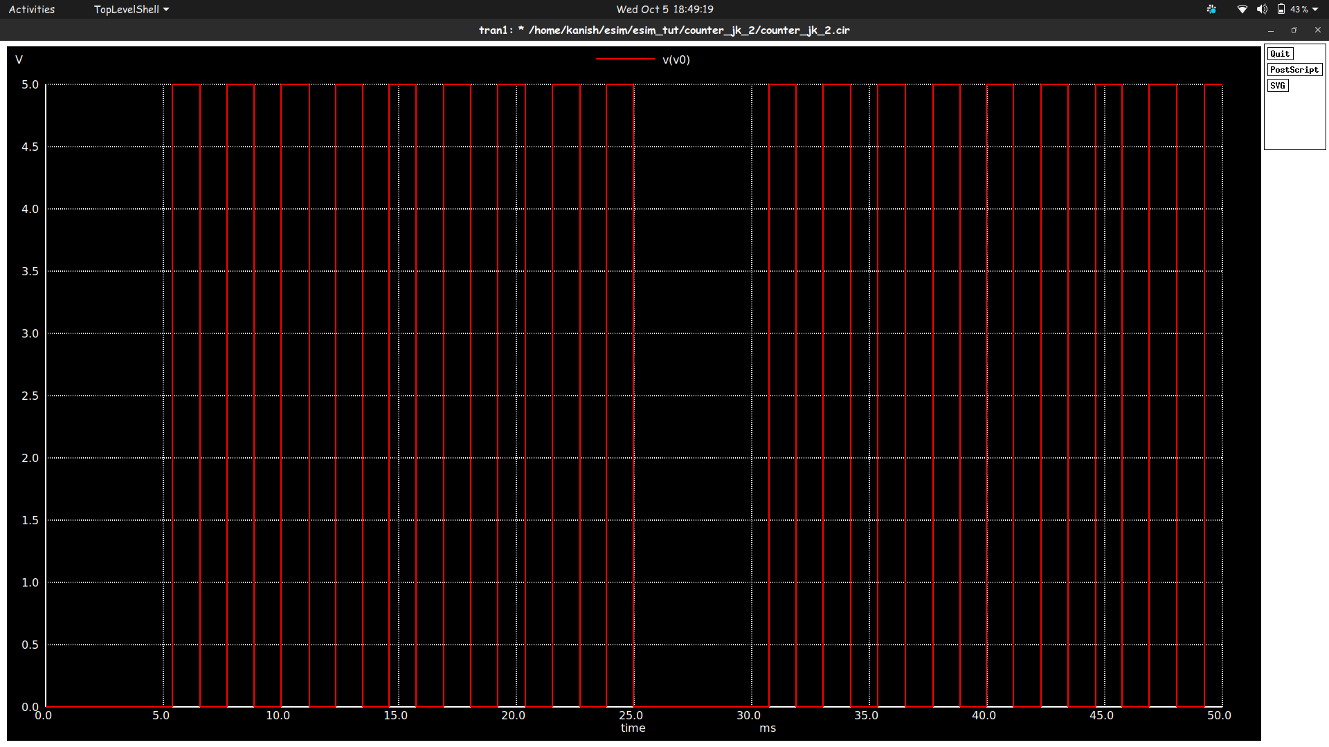
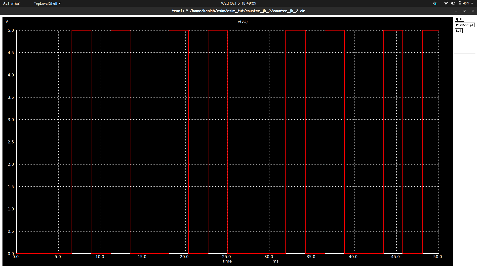
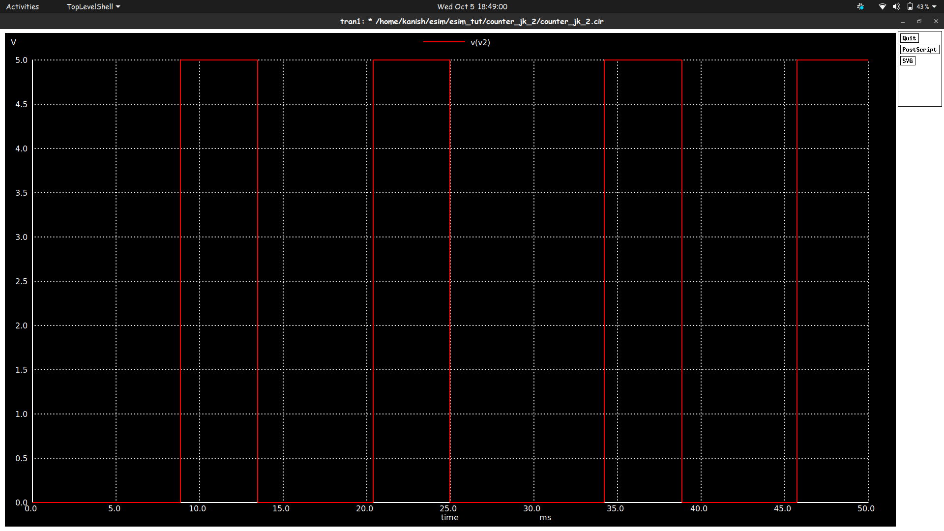
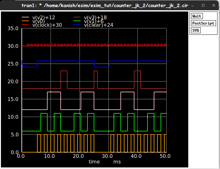
The following waveforms are the ngspice plots for the designed circuit :
Clear Signal
 Clock Signal
 Q0 Output
 Q1 Output
 Q2 Output
 Q3 Output
 Combined Waveform
- Open eSim
- Run NgVeri-Makerchip to create a digital block
- Add top level verilog file in Makerchip Tab
- Click on NgVeri tab and add dependency files
- Click on Run Verilog to NgSpice Converter
- Debug if any errors
- Model created successfully
- Open a new terminal
- Clone this project using the following command:
git clone https://github.com/KanishR1/MOD_10_Sync_Counter_Mixed_sig_SoC.git - Change directory:
cd eSim_project_files/counter_jk_2 - Run ngspice:
ngspice counter_jk_2.cir.out - To run the project in eSim:
- Run eSim
- Load the project
- Open eeSchema
- FOSSEE, IIT Bombay
- Steve Hoover, Founder, Redwood EDA
- Kunal Ghosh, Co-founder, VSD Corp. Pvt. Ltd. - [email protected]
- Sumanto Kar, eSim Team, FOSSEE
- Morris Mano & Michael D Ciletti, “Digital Design: With an Introduction to Verilog HDL, 5th Edition, Pearson Education, 2013
- Neil H.E. Weste, David Money Harris ―CMOS VLSI Design: A Circuits and Systems Perspective.
- https://skywater-pdk.readthedocs.io/en/main/
- https://www.homemade-circuits.com/cmos-astable-bistable-monostable-circuits-explained/
- https://www.youtube.com/watch?v=M8EqkE4G9IE&ab_channel=SimplyPut
- https://github.com/Eyantra698Sumanto/Two-in-One-Low-power-XOR-XNOR-Gate.git