
UNIVERSITY OF WEST ATTICA
SCHOOL OF ENGINEERING
DEPARTMENT OF COMPUTER ENGINEERING AND INFORMATICS
University of West Attica · Department of Computer Engineering and Informatics
Electronics
Vasileios Evangelos Athanasiou
Student ID: 19390005
Supervision
Supervisor: Panagiotis Giannakopoulos, Professor
Supervisor: Ioannis Amorginos, Applications Lecturer
Co-supervisor: Eleni Tsalera, Academic Scholar
Co-supervisor: Michalis Diamantopoulos, Applications Lecturer
Athens, November 2022
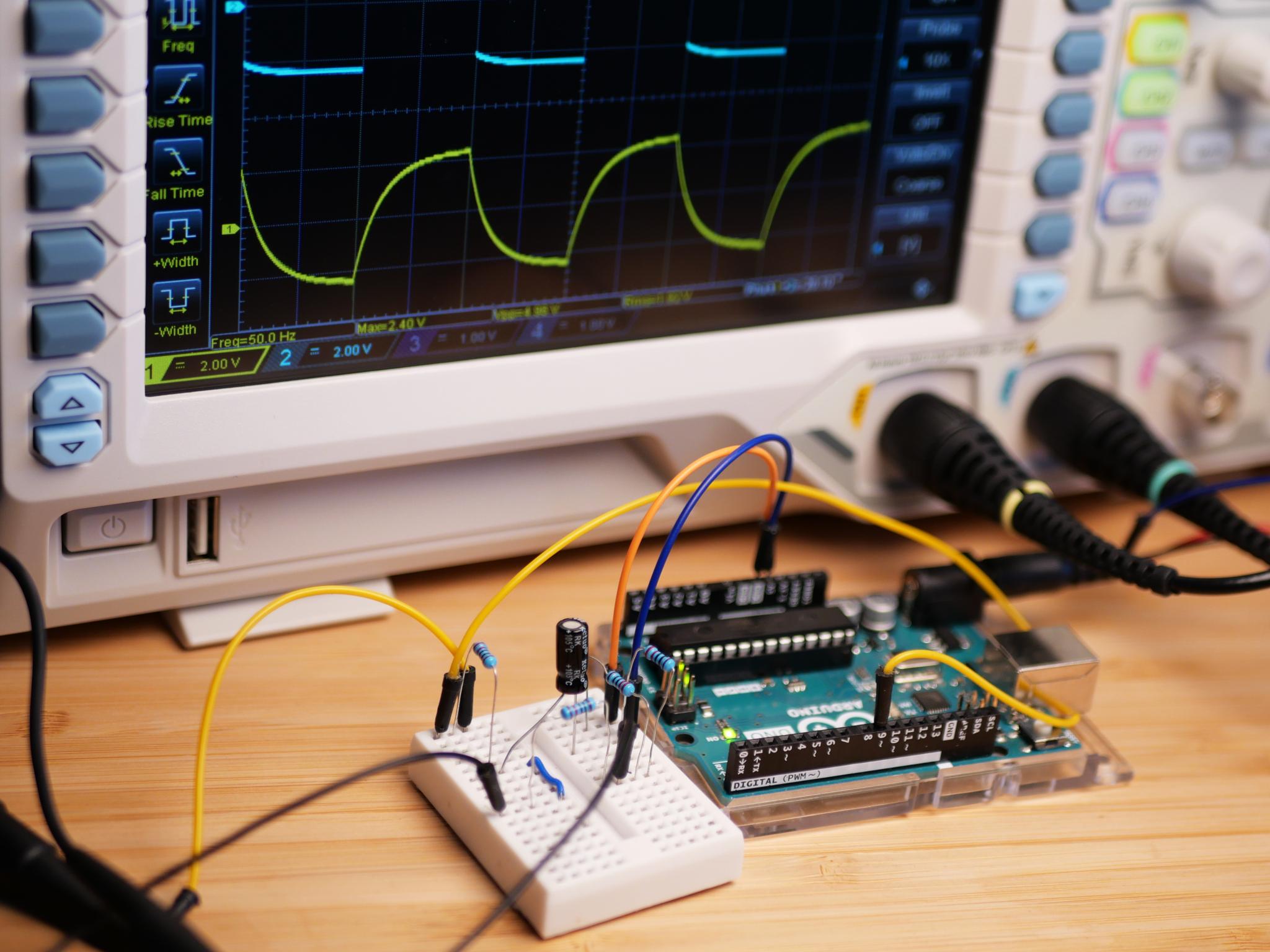
This README provides an overview of Lab 1, submitted for the Electronics course at the University of West Attica. The lab focuses on resistor measurements, D.C. voltage, and A.C. signal analysis.
| Section | Folder / File | Description |
|---|---|---|
| 1 | assign/ |
Assignment documents |
| 1.1 | assign/Exercise-1st-Resistance-and-Oscilloscope.pdf |
Assignment instructions (English) |
| 1.2 | assign/Άσκηση-1η-Αντιστάσεις-και-Παλμογράφος.pdf |
Assignment instructions (Greek) |
| 2 | components/ |
Lab components and equipment photos |
| 3 | docs/ |
Theory and reference documents |
| 3.1 | docs/Resistance-and-Oscilloscope.pdf |
Theory (English) |
| 3.2 | docs/Αντιστάσεις-και-Παλμογράφος.pdf |
Theory (Greek) |
| 4 | multisim/ |
Multisim projects and screenshots |
| 4.1 | multisim/Screenshots/ |
Screenshots of Multisim simulations |
| 4.2 | multisim/*.ms14 |
Multisim project files |
| 5 | photos-in-lab/ |
Photos of lab setup and measurements |
| 6 | visio/ |
Visio diagrams for circuits and measurements |
| 7 | README.md |
Project documentation |
| 8 | INSTALL.md |
Usage instructions |
- Analog & Digital Training System: MCP M21-7000A
- Breadboard: M21-7000A
- Oscilloscope: HAMEG HM203-5
- Digital Multimeter: MT8045
- Resistors: 1 kΩ, 27 kΩ, 39 kΩ
-
Resistor Resistance Measurement
Calculate and measure resistor values using:- Color codes
- Theoretical formulas
- Simulation software
-
D.C. Voltage Measurement
Analyze and measure direct current both theoretically and experimentally. -
A.C. Measurement
Measure signal period and calculate frequency.
The equivalent resistance for resistors in parallel was calculated.
For a 1 kΩ and a 27 kΩ resistor in parallel:
- Simulation Result (Multisim): 964.286 Ω
Actual measurements differed slightly due to resistor tolerance ±5% (gold stripe):
- 1 kΩ Resistor: 0.9893 kΩ
- 27 kΩ Resistor: 27.12 kΩ
- 39 kΩ Resistor: 38.43 kΩ
These results confirm that both theoretical calculations and simulations closely match practical measurements.