Vespera is a Latin word for "evening", derived from vesper, which also refers to the evening star, the planet Venus as it appears in the twilight sky. The light represents the passage of time and the transition from day to night, the moment when a single point of light becomes visible against the fading horizon.
Vespera is a WiFi-enabled luminaire that can be controlled via MQTT messages. It is the basis for the workshops in CASA0014 - Prototyping the Internet of Things. This repository contains the following key resources:
- The main Arduino demo sketch for the workshops
- Code for web visualiser
- Python examples (just for fun)
- Test scripts used during development
- The Vespera Arduino code
- The Arduino code used for the student selector
- Lots of pictures on Flickr
This system allows multiple devices to control the Vespera light installation remotely via MQTT. The core components are the Vespera light itself which is running on an Arduino MKR1010 and a separate Arduino-based dial that is used to define which topic Vespera should listen to. In addition a variety of interfaces have been created as demo examples of how to interface with the light - they include an Arduino Feather M0 tilt controller, some Python scripts and a web viewer to mimic the output sent to Vespera. All communication is routed through our MQTT broker (mqtt.cetools.org) over wifi.
Vespera (Arduino MKR1010): This is the central light installation. It receives RGB color data via MQTT messages and uses this information to control its 72 NeoPixel LEDs. It subscribes to specific MQTT topics to receive its commands student/CASA0014/luminaire/. Note: the code on this device is shared for information but cannot be changed by students.
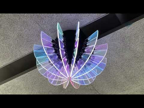
Vespera - YouTube
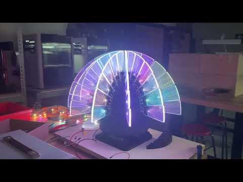
Vespera WIP - YouTube
Arduino Dial: This is a separate input device. It publishes a message to the MQTT broker that specifies which user's color message should be displayed on Vespera, effectively acting as a selection switch.

Tilt Controller (Arduino Feather M0): This physical device is used to generate and send RGB color values to the MQTT broker. It publishes messages to topic student/CASA0014/luminaire/0.

Python Script: A software-based client that can also publish RGB color data to the same MQTT broker, allowing for automated or scripted control of the Vespera.
MQTT Broker (mqtt.cetools.org): This is the central hub for all communication. It receives messages from the controller, Python script, and dial, and then forwards them to Vespera. It ensures that all components can communicate without being directly connected to each other.
Web Visualise: A web-based interface that mimics the output sent to Vespera. It subscribes to the same MQTT topic and displays the color data in a browser, providing a visual representation of what Vespera would display. This means you can visualise the output of your Arduino device without needing access to Vespera - hence allowing you to all work in parallel. The code for the HTML / JS web interface tis shared for information but we do not anticipate you developing this as part of your course work.

The CASA0014 workshop walks through the steps needed to create your own arduino based controller to send messages to Vespera.
Use the "Selector" dial to choose your user number (1-40, the allocations will be listed on Moodle). This will set the topic that Vespera is listening to. This means that only one user can control Vespera at any one time!
Use the web visualiser to see the output of your code. The web visualiser is a simple HTML / JS page that connects to the same MQTT broker as Vespera and displays the colour messages it receives. This means you can see the output of your code without needing access to Vespera - hence allowing you to all work in parallel.
In the mqtt_callback function of the Vespera code, the payload array contains the binary RGB values for each LED. Each LED's color is defined by three consecutive bytes: Red, Green, and Blue. The values for each color component range from 0 to 255.
Here are some examples of what those r, g, and b byte values would represent:
Red (full brightness): R = 255 G = 0 B = 0
In the payload, this would be FF 00 00 (hexadecimal)
Green (full brightness): R = 0 G = 255 B = 0
In the payload, this would be 00 FF 00 (hexadecimal)
Blue (full brightness):R = 0 G = 0 B = 255
In the payload, this would be 00 00 FF (hexadecimal)
White (full brightness): R = 255 G = 255 B = 255
In the payload, this would be FF FF FF (hexadecimal)
Black (off): R = 0 G = 0 B = 0
In the payload, this would be 00 00 00 (hexadecimal)
Purple: R = 128 (mid red) G = 0 B = 128 (mid blue)
In the payload, this would be 80 00 80 (hexadecimal)
The message payload is structured as a byte array of these RGB triplets for each LED in the luminaire. For example, if the luminaire has 72 LEDs, the payload would contain 216 bytes (72 LEDs * 3 bytes per LED).
The format is hard to read in a tool like MQTT Explorer as it shows the raw byte values. However, you can convert these byte values to hexadecimal or decimal to understand the color values being sent to each LED. A sample byte array payload is as follows - in this case an example of all red values:
(bytearray(b'\xff\x00\x00\xff\x00\x00\xff\x00\x00\xff\x00\x00\xff\x00\x00\xff\x00\x00\xff\x00\x00\xff\x00\x00\xff\x00\x00\xff\x00\x00\xff\x00\x00\xff\x00\x00\xff\x00\x00\xff\x00\x00\xff\x00\x00\xff\x00\x00\xff\x00\x00\xff\x00\x00\xff\x00\x00\xff\x00\x00\xff\x00\x00\xff\x00\x00\xff\x00\x00\xff\x00\x00\xff\x00\x00\xff\x00\x00\xff\x00\x00\xff\x00\x00\xff\x00\x00\xff\x00\x00\xff\x00\x00\xff\x00\x00\xff\x00\x00\xff\x00\x00\xff\x00\x00\xff\x00\x00\xff\x00\x00\xff\x00\x00\xff\x00\x00\xff\x00\x00\xff\x00\x00\xff\x00\x00\xff\x00\x00\xff\x00\x00\xff\x00\x00\xff\x00\x00\xff\x00\x00\xff\x00\x00\xff\x00\x00\xff\x00\x00\xff\x00\x00\xff\x00\x00\xff\x00\x00\xff\x00\x00\xff\x00\x00\xff\x00\x00\xff\x00\x00\xff\x00\x00\xff\x00\x00\xff\x00\x00\xff\x00\x00\xff\x00\x00\xff\x00\x00\xff\x00\x00\xff\x00\x00\xff\x00\x00\xff\x00\x00\xff\x00\x00\xff\x00\x00\xff\x00\x00\xff\x00\x00\xff\x00\x00'))
Gosund at http://10.129.118.101