Home
Also see the other pages documenting the individual features.
In the following, we will used LMB for the left mouse button, MMB for middle mouse button, and RMB for the right mouse button. Usually it is meant that you click with with the respective button to activate the functionality.
When loading a dataset, the data must be organized as follows:
point cloud folder
├── velodyne/             -- directory containing ".bin" files with Velodyne point clouds.
├── labels/   [optional]  -- label directory, will be generated if not present.
├── image_2/  [optional]  -- directory containing ".png" files from the color camera.
├── image_3/  [optional]  -- directory containing ".png" files from the other color camera (there are stereo cameras mounted on the car).
├── calib.txt             -- calibration of velodyne vs. camera. needed for projection of point cloud into camera.
└── poses.txt             -- file containing the poses of every scan, see below on how to obtain them.
The velodyne folder contains the Velodyne scans in the KITTI .bin format, i.e., just binary floats, where each point is represented by 4 consecutive floats (x,y,z,remission). The calib.txt contains the transformation from the Velodnye to the cameras, which is needed to convert the poses in poses.txt. We kept the original convention that the ground truth poses are given in the camera coordinate system. Thus each pose is transformed via T.inv() * pose * T into the velodyne coordinate system, where T corresponds to the transformation from Velodyne to camera coordinate system. The poses.txt contains the pose for each scan, which is applied before visualizing the points.
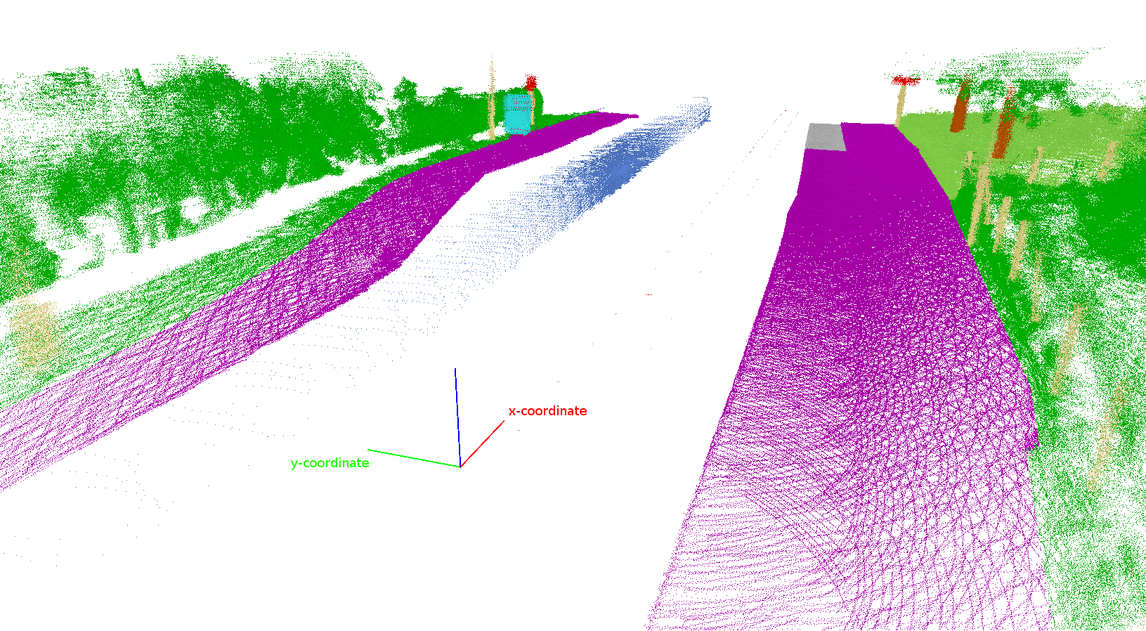
There are three colored vectors which in the tile-coordinate system correspond to:
- red vector for the x-direction
- green vector for the y-direction
- blue vector for the z-direction
In the console output you will see the tile-coordinates of the currently selected tile.
For example, 200, -100, 50 denotes the tile at
x = 200 (red direction), y = -100 (green direction) with tile size = 50.
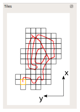
As the whole point cloud contains billions of points, we use a tile to represent a small part of the point cloud. In the tile selection view on the left side, you can select square to load all point inside the selected tile. The currently selected tile is highlighted by a orange border.
The red line running through the tiles shows the path of the car driving through the scene.
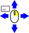
You have to hold the Ctrl-button for moving around in the scene. Moving is still possible even while having the brush or polygon tool selected.
The following actions will change the viewpoint of the camera:
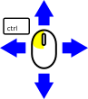 |
Move in the x-y-direction relative to the camera angle (stay in z=constant plane) |
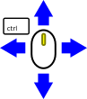 |
Move in the y-z-direction relative to the camera angle (stay in x=constant plane) |
 |
Change viewing angle of the camera |
 |
Zoom in/out |
The following actions will change the viewpoint of the camera:
|
Rotate camera |
|
Translate camera relative to the camera view |
|
Zoom in/out |