News: new telegram group for BACCABLE: https://t.me/baccable Please read this page and watch all youtube playlist videos before ask. Plase continue to donate to allow me to do not loose interest on this project: https://www.paypal.me/tr3ma1
Now you can donate in Crypto too.
Bitcoin: bc1qyvh5mexkhfw6tgdztm884gs9y6smc04lueyvth

BACCABLE is a project developed exclusively for educational and research purposes. The use of this tool on vehicles operating on public roads or in any context that may cause harm to people, property, or violate applicable regulations is strictly prohibited.
The author of this project assumes no responsibility for any damages, malfunctions, or consequences resulting from the use of BACCABLE. The end user bears full civil, criminal, and legal responsibility for its use.
It is strongly recommended not to use this project in real-world vehicle applications.
BACCABLE è un progetto sviluppato esclusivamente a scopo didattico e di studio. È severamente vietato utilizzare questo strumento su veicoli in circolazione su strade pubbliche o in qualsiasi contesto che possa causare danni a persone, cose o violare normative vigenti.
L'autore del progetto non si assume alcuna responsabilità per eventuali danni, malfunzionamenti o conseguenze derivanti dall'uso di BACCABLE. L'utilizzo di questo strumento è interamente a rischio dell'utente finale, che si assume ogni responsabilità civile, penale e legale.
Si raccomanda di non impiegare questo progetto in applicazioni reali su veicoli.
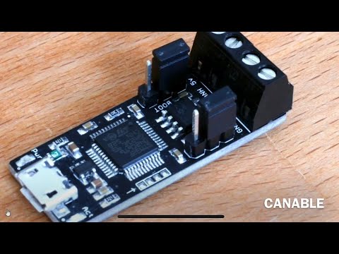
This project uses the famous CANABLE (the cheapest can bus device on the market) in order to:
- sniff on the can bus (useful for debug and exploit purposes)
- decode and store some parameters sniffed on the bus (like motor rpm, accelerator pedal position and gear selection)
- control a WS281x leds strip by means of the decoded can bus data, then lighting the leds strip according to accelerator pedal position and gear selection.
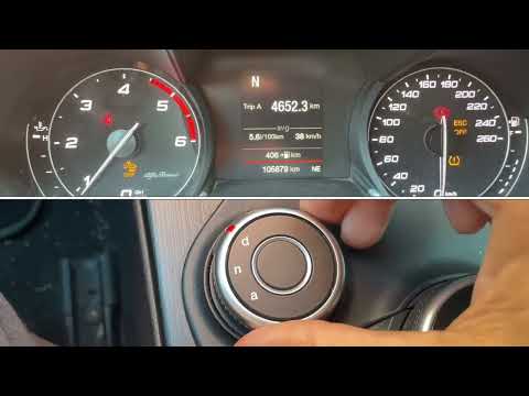
- automatically disable start&stop car functionality
- act as Immobilizer, by injecting can bus messages when required.
- show SHIFT warning indicator on dashboard when configurable motor rpm speed is overcomed
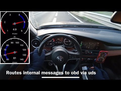
- add a menu to dashboard in order to show additional parameters like dpf occlusion percentage, oil pressure and performance statistics
- route native messages encapsulating them in uds parameter response, in order to make them available to diagnostic requests performed with OBD (you can get parameters commonly not available in OBD apps).
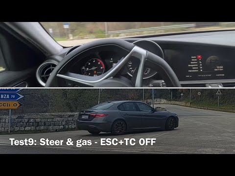
- enable and disable ESC and TC with left stalk button press
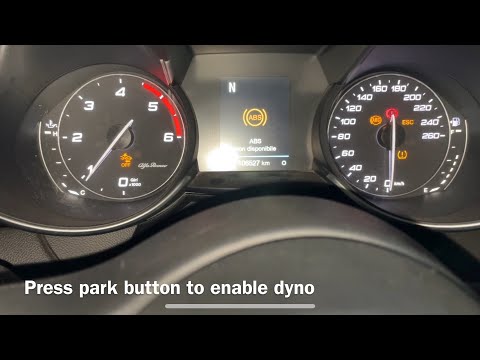
- Dyno mode disables ESC,TC,ABS. All main controls are disabled and it works on stock giulia too.
BACCABLE overview (click on the following image to see the video) (note: video not updated. do not includes all the functionalities added to the device last months)
Link to youtube videos playlist:
https://www.youtube.com/playlist?list=PLBaS0780TbwKpBBER44QJkiz-0hAlga8X
I started the development from the famous SLCAN firmware (https://github.com/normaldotcom/canable-fw), by porting it inside stm32Cube environment (I updated usb interface), then I added:
- message decoding (watch the following video)
- leds Controlling function (watch the following video) NOTE: video was not updated after firmware optimization. Now you have to uncomment the define LED_STRIP_CONTROLLER_ENABLED in order to use the led controlling functionality
- start&stop car function disabler (more detailes in the dedicated subparagraph),
- immobilizer (more details in the dedicated subparagraph)
- SHIFT warning indicator on dashboard (more detailes in the dedicated subparagraph),
- ESC and TC controller (more detailes in the dedicated subparagraph)
- show parameters on dashboard (more detailes in the dedicated subparagraph)
- Subfolder firmware contains the firmware
- Subfolder hardware/canable contains canable board layout and pcb wiring diagram. It comes from https://github.com/makerbase-mks/CANable-MKS. There are different designs of canable, but theay are all similar.
- Subfolder hardware/box contains the 3d model of the cases to accomodate required components.
- Subfolder hardware/system interconnection contains interconnection diagram to connect required components
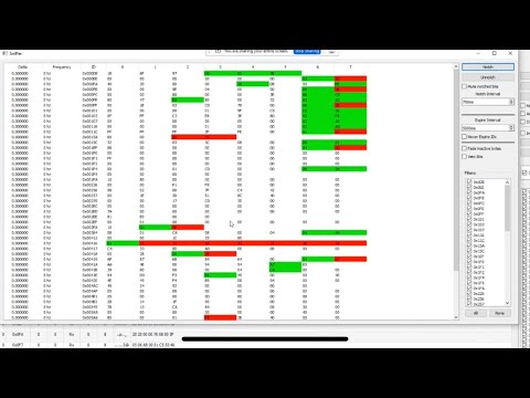
- Subfolder tools contains the famous savvyCan sniffer tool for windows (portable) and excel sheet used to calculate pwm and clocks settings.
The new functionality "car start&stop disabler" (#define SMART_DISABLE_START_STOP) is implemented by simply sending the expected message on C1 can bus. The function is firedonly once, after at least 30 seconds from the switch on and only if engine is on and only if start&stop is active.
The old functionality "car start&stop disabler" (#define DISABLE_START_STOP) is implemented by simply shorting a gpio to ground trough a resistor (if the motor is rotating), in order to simulate Start&Stop button press on the car panel, with a delay after the device was switched on. I avoid to do anything if a specific can bus message tells me that the the Start&Stop was still manually disabled by the pilot. The used resistor is suitable for my car. I left this function just in case of problems withe new smart developed function (see next point)
Note: This projet was tested on alfaromeo Giulia. Each one of you, if dealing with other car, different than Alfaromeo Giulia/Stelvio, should:
- perform some checks on the panel with a multimeter, in order to find the proper resistor value for the start&stop button.
The following video shows the improvement from the old car start&stop to the new one:
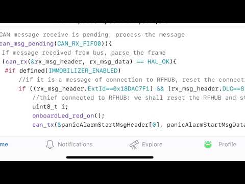
The functionality IMMOBILIZER performs the following:
- Detects if the thief is trying to connect to to RFHUB (they do it to add a key to the car)
- Starts the Panic Alarm after one second
- Continuously Resets the RFHUB in order to reset the thief connection, with this message for 10 seconds
- after 10 seconds stops to send messages and stops alarm, and return listening for thief messages
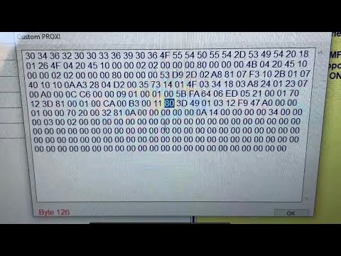
Note1: Panic alarm will start only if you previusly enabled panic alarm in your ECU, with the MES proxy alignment procedure shown in this video:
Note2: The Immobilizer functionality will not detect the thief if you power the BACCAble with a voltage available only when the panel is switched on. Therefore, if you use immobilizer function, you shall remove the voltage regulator that I use to convert the 12V to 5V and directly plug the canable to the 5V usb voltage taken from the connector of the USB interface in the central area, close to cigarette lighter socket. In fact, usb voltage is switched on as soon as the thief wakes up the rfhub.
Note3: As alterinative for immobilizer, you can use the DCDC connected to a 12V of the car always available, to ensure roper working of the immobilizer. Current consumption is low but I recommend to avoid a device always draining current from your battery.
Note4: Once we start to send the rfhub reset message, neither the injition button will work. the car will appear as dead..
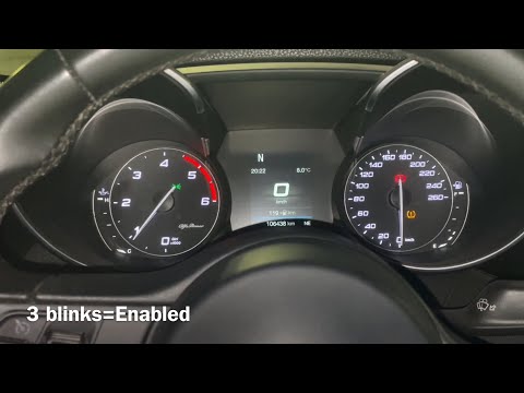
Note5: immobilizer at the beginning is enabled by default. To permanently toggle the status you shall be with motor on, cruise control disabled, neutral gear, press cruise control gentle speed up for around 30 seconds. If the immo becomes disabled, it will be blink the dashboard brightness for 5-6 times. If immo becomes activates, the dashboard will blink 3 times. The change is persistent after a power loss.
Note6: when you plug the power to baccable, if immobilizer is enabled, the blue led on canable (on fysect ucan leds are both red and we shall talk about the led far from usb port ) will blink twice and the dashboard will blink once. Thisis useful to understand how the immobilizer is set.
The following video shows the improvement to immobilizer functionality (second half of the video):
The leds strip is lighted accordingly to the movement of the accelerator pedal and the gear selection.
This projet was tested on alfaromeo Giulia. Each one of you, if dealing with other car, should:
- identify proprietary can bus messages, by sniffing data with savvycan. Note: this works only if baccable is connected to C1 can bus.
The SHIFT warning indicator function allows you to show on dashboard (only if you are in race mode) the SHIFT warning label when configurable motor rpm speed is overcomed (3 levels of warning). The following video explains the behavious and the code description:
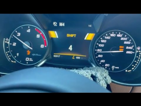
Note1: this works only if you previously enabled race mode with proxy alignment (or if you have a Quadrifoglio) Note2: this works only if baccable is connected to C1 can bus.
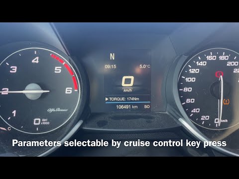
Adds a menu to the dashboard allowing the user to show additional parameters.
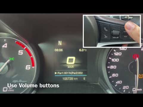
I made a first test using right wheel side buttons (radio volume buttons) (decoded on BH can bus) but then I changed it, and now I'm using buttons on the left side of the wheel (cruise control buttons) (decoded on C1 can bus).
This is the reason why in the following old video you will see using volume buttons
I leave the following video just for reference, to track the history.
Now in the code I use cruise control button to move in the menu. Two baccable shall be connected between them: the slave baccable shall be connected to BH can bus (in example on OBD port, pins 3 and 11) and the master baccable shall be connected to C1 can bus. The master baccable shall be set with the #define SHOW_PARAMS_ON_DASHBOARD_MASTER_BACCABLE, while the slave shall be set with #define SHOW_PARAMS_ON_DASHBOARD. The slave receives data from master baccable and displays messages on dashboard, while the master gets the parameters on C1 bus and sends them to slave baccable. Unfortunately st32f072 can not work as usb host but only as usb devce, therefore the communication between baccable is implemented with half duplex serial line (uart) on a single wire. it works really fine.
This diagram shows the required connections for this function to work:

this video shows the new functionality:
The new commands implemented on the master canable are the following: by default the menu on dashboard is disabled
- To enable it you shall be with engine on and cruise control disabled. Press RES button on the wheel for around 2 seconds and the menu will popup the the baccable version (currently under deveolpement therefore you just receive a string on the usb opened with a terminal window.
- To move inside menu use the cruise control up and down buttons (gentle press moves by 1 parameter, strong press moves by 9 parameters) in a rotational menu.
- when you enable cruise control the menu controls are disabled but the last set parameter remains on screen.
- parameters are updated each 500 msec
- to disable the menu just disable cruise control and press RES button for at least 2 seconds.
By uncommenting the #define ROUTE_MSG in main.h, you can route native messages encapsulating them in uds parameter response, in order to make them available to diagnostic requests performed with OBD (you can get parameters commonly not available in OBD apps). This functionality performs the following: Upon receive of UDS request with message id 0x18DABAF1 having message data 0622xzyyyyyyyy, Baccable will understand the following:
- 0x18DABAF1 identifies that the message is a Route request (request to route a native message to the diagnostic)
- The route is done just one time (one packet) to avoid bus flood, and it routes only 5 bytes of the requested message
- x (first nibble of third byte of the can message) can be 0 (std Id) or 1 (Ext Id).
- y (second nibble of third byte of the can message) is the offset of the message to route. the number of bytes routed will be only 5. offset will set the part of the message to route
- yyyyyyyy is the requested msg id right aligned.
- If you uncomment this functionality, BACCABLE will by default open a connection at 500kbps (suitable for C1 and C2 bus)
Example1:
		Diagnostic sends msgID 0x18DABAF1 with data 062201000004B2

		BACCABLE replies msgID 0x18DAF1BA with data 076201AABBCCDDEE  where AA is the second byte of the original 0x4b2 message
Example2:
		Diagnostic sends msgID 0x18DABAF1 with data 062210E10204B2

		BACCABLE replies msgID 0x18DAF1BA with data 076210AABBCCDDEE  where AA is the first byte of the original 0xE10204B2 message
The following image summarize the functionality:

The following video shows this functionality in use with carscanner and it explains in detail how it works:
By pressing left stalk button (LANE indicator) for 2 seconds, in D,N,A modes the ESC and TC will be disabled. Changing DNA mode or pressing again the same button, it is possible to revert the change. In Race mode, where ESC and TC ar tipicalliy disabled, this functionality allows to enable ESC and TC. Note1: this works only if you previously enabled race mode with proxy alignment (or if you have a Quadrifoglio) Note2: this works only if baccable is connected to C2 can bus. The following video explains the behavious and the code description:
The following video shows tests performed on this functionality on the road:
Dyno mode disables ESC,TC,ABS. All main controls are disabled and it works on stock giulia too. It is activated and deactivated with park button pressed for few seconds.
The following video shows how to enable and disable it:
You should perform some preliminary settings inside firmware:
- If you want to use the device as usb can bus sniffer you shall uncomment #define ACT_AS_CANABLE in main.h (better if you comment the other functionalities defines to reduce computational charge). Generally speaing if you use other functions, the ACT_AS_CANABLE shall remain commented otherwise the device don't properly work in some situations.
- If you want to use the device as leds strip controller you shall uncomment the line " #define LED_STRIP_CONTROLLER_ENABLED " in main.h (this was tested only connected to C1 can bus)
- If you want to use the old piece of code that disables the car start&stop at the power on by means of an external resistor connected close to the button defined in the interconnection diagram, you shall uncomment #define DISABLE_START_STOP in main.h (this works only if connected to C1 can bus because I check motor speed. If someone wants it on another can bus, he shall remove the motor speed check)
- if you want to disable new function start&stop disabler that acts only by sending a message on C1 can bus, comment the #define SMART_DISABLE_START_STOP in main.h
- If you want to disable IMMOBILIZER functionality, you shall comment #define IMMOBILIZER_ENABLED in main.h (this works only if connected to C1 can bus)
- In vumeter.c you shall set the number of leds in your leds strip, by modifing the following line: #define MAX_LED 46
- If you want to use SHIFT WARNING INDICATOR functionality, you shall uncomment #define SHIFT_INDICATOR_ENABLED in main.h and set the define SHIFT_THRESHOLD to the rpm speed at which the indicator will start to be shown (2000rpm by default) (works only in race mode, and was tested only connected to C1 can bus)
- If you want the capability to enable and disable TC with left stalk button, you shall uncomment #define ESC_TC_CUSTOMIZATOR_ENABLED in main.h and connect the baccable to C2 can bus (pin 12 and 13 of the OBD port)
- If you want to add menu on the dashboard to display additional parameters, you shall uncomment #define SHOW_PARAMS_ON_DASHBOARD in main.h, for the slave canable connected to BH can bus (in example on OBD port, pins 3 and 11) and connect another canable to C1 can bus to act as the master. The master canable shall be set with the #define SHOW_PARAMS_ON_DASHBOARD_MASTER_BACCABLE. The slave receives data from master canable and display it on dashboard, while the master gets the parameters on C1 bus and sends them to slave canable.
- I found that fysect ucan board has leds connecetd in a different manner so that a inversion on the control of the internal transistors are required. So if you use fysect ucan board don't forget to uncomment #define UCAN_BOARD_LED_INVERSION
Note: immobilizer at the beginning is enabled by default. To permanently toggle the status you shall be with motor on, cruise control disabled, neutral gear, press cruise control gentle speed up for at around 30 seconds. If the immo becomes disabled, it will be blink the dashboard brightness for 5-6 times. If immo becomes activates, the dashboard will blink 3 times. change is permanent after a power loss.

Note: compile the code in Release version and not debug since Release version is much more light (smaller elf file size). Some of BACCABLE videos shows how to compile.
Software to use:
- use stm32CubeIde to compile on windows
- use stm32CubeProgrammer to flash the firmware elf file contained in subfolder firmware\ledsStripController\Release
Note: i downloaded previous version of the programmer (v.2.15.0) since last available revision had some bug that won't allow me to flash canable. Edit: now also last version can be used.
Flash procedure:
- press reset button on the canable, then connect usb to pc (the canable will be detected as serial device named "stm32 bootloader"
- use stm32CubeProgrammer to flash the device using the file ...firmware\ledsStripController\Release\ledsStripController.elf
click on the following image to see the full hardware and interconnections video:
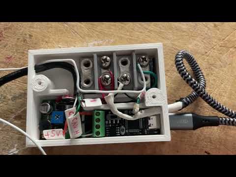
Used hardware:
Canable: This is the first I purchased (https://a.aliexpress.com/_Ev1yBz1 ) Generally speaking I found these compatible devices (It is important that the chip is a stm32F072):
- Original MKS Canable
- Canable DykbRadio Nano
- Fysect ucan
- candlelight small board ( [https://github.com/linux-automation/candleLightFD](https://github.com/linux-automation/candleLight/) )
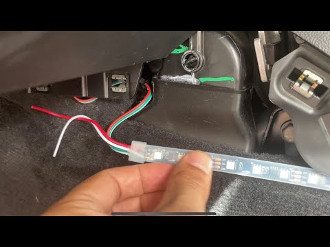
Leds Strip ws2811 ip65: https://www.ebay.it/itm/325563557492?mkcid=16&mkevt=1&mkrid=711-127632-2357-0&ssspo=wTLp3UyoQGK&sssrc=4429486&ssuid=zXyeQJ2cSnu&var=514593107226&widget_ver=artemis&media=COPY
Amazon alternatives: Canable: https://amzn.to/3zzeNMq Leds strip: https://amzn.to/3W3TifJ
Note: use recommended canable links cause some of them uses different st chip and I'm not sure if other chips are supported.
Since I found how to disable Start&Stop by only sending can message, the new required connections are just: CAN bus from canable to car (termination board on canable) and power supply from usb hub 5V usb to the usb port of the canable. If you enable the function to control a led strip, the usb data shall be connected to led strip, as defined in the old schematic here reported for reference. If you use the function to show params on dashboard, you have to add the wire between the 2 boards (watch the diagram in the DASHBOARD MENU functionality section of this page.
Note: In "Usage Instructions" section it is defined when you need to connect to a different can bus. The following old diagram shows the connection to C1 can bus (pin 6 and 14 of the OBD port), commonly used for immobilizer,start&stop, leds strip controller and other functionalitites, but there are also C2 can bus (pin 12 and 13 of the OBD port) required in example for ESC&TC disabler functionality and BH can bus (pin 3 and 11 of the OBD port) for the functionality to add parameters on the dashboard). This is the old original wiring diagram:

Note: if you use immobilizer function, it is suggested to remove the voltage regulator that I used to convert the 12V to 5V and directly plug the CANABLE to the 5V usb voltage, taken from the connector of the USB interface in the central area, close to cigarette lighter socket. As alterinative for immobilizer, use the DCDC connected to a 12V of the car always available, to ensure proper working of the immobilizer. Current consumption is low but I recommend to avoid a device always draining current from your battery.
I developed different cases. New single case for original canable or DykbRadio Nano canable:


New single case for Fysect Ucan: (uses same case of dual ucan with a dedicated cap)

New Dual case for Fysect Ucan (to accomodate 2 ucan, each one connected to a different can bus):

Old box to accomodate DCDC, termination board and original canable or DykbRadio Nano canable.


OLD: watch the following video to see installation procedure. note: the video doesn't show the connection from usb +5V required to use immobilizer function.
The following video will show the structure of the firmware.
Note: the video was made before to update the method to send rfhub reset message for 10 seconds, and before of the code optimization in the main loop, and before latest functionalities were added.
when configured as canable the firmware acts as the classic SLCAN firmware. it means that you can use it with a pc equipped with savvycan tool, in order to sniff packets in the canbus. With such configuration the device is seen by the pc as a virtual serial port implementing the following serial commands:
- O - Open channel
- C - Close channel
- S0 - Set bitrate to 10k
- S1 - Set bitrate to 20k
- S2 - Set bitrate to 50k
- S3 - Set bitrate to 100k
- S4 - Set bitrate to 125k
- S5 - Set bitrate to 250k
- S6 - Set bitrate to 500k
- S7 - Set bitrate to 750k
- S8 - Set bitrate to 1M
- M0 - Set mode to normal mode (default)
- M1 - Set mode to silent mode
- A0 - Disable automatic retransmission
- A1 - Enable automatic retransmission (default)
- TIIIIIIIILDD... - Transmit data frame (Extended ID) [ID, length, data]
- tIIILDD... - Transmit data frame (Standard ID) [ID, length, data]
- RIIIIIIIIL - Transmit remote frame (Extended ID) [ID, length]
- rIIIL - Transmit remote frame (Standard ID) [ID, length]
- V - Returns firmware version and remote path as a string Note: Channel configuration commands must be sent before opening the channel. The channel must be opened before transmitting frames.
This firmware currently does not provide any ACK/NACK feedback for serial commands.
The approach used to control WS281x leds strip controller was derived from this: https://github.com/MaJerle/stm32-ws2811-ws2812-ws2812b-ws281x-tim-pwm-dma-timer where it is used a timer to start a pwm, then DMA allows a fast change of the duty cycle of the pwm.
Summarizing, the ws281x uses a control signal where each bit is transmitted as 1 or 0 with a pwm signal (with 2 different duty cycle for 0 and for 1 logic levels). The ws281x protocol expects a 24 bits sequence (3x8) for each led, where each 8 bits defines a color (red, green and blue). First led will get the first 24 bits, then it sends the rest to the next led. each led does the same. A pause in the transmission determines the end of the frame, then a new frame can be sent. The protocol and the timings are described in the ws281x datasheet
WS2811 and WS2812 protocol is specific one and has defined values:
- Transfer rate is
800 kHz, or1.25uspulse length for each bit - Transfer length is
24pulses for each led, that's30usfor one LED - Each logical bit (
1or0) consists of high and low part, with different length - Reset pulse is needed prior updating led strip, to synchronize sequence

Minimum reset pulse length depends on WS281x device. Check datasheet for your particular unit. WS2812B says
> 50us, while WS2811 says> 280us.
DMA controllers in STM32s support various operations, one of them being super handy for our WS LED driver, called circular operation mode. Circular mode will continuously transmit data from memory to peripheral (or, in general, can also go opposite direction) and periodically send transfer-complete or half-transfer-complete interrupts to the application.

We will use HT and TC events extensively, as they will be use to prepare data for next operations to transfer all bits for all leds.
These areinformation that I found. Use everything this at your own risk.
-
msg id 0x90 prints text on dashboard (on BH can bus) and contains:
- total frame number is on byte 0 from bit 7 to 3
- frame number is on byte 0 from bit 2 to 0 and byte1 from bit7 to 6
- infoCode is on byte1 from bit 5 to 0 (0x12=phone connected, 0x13=phone disconnected, 0x15=call in progress, 0x17=call in wait, 0x18=call terminated, 0x11=clear display, ...)
- /UTF text 1 is on byte 2 and byte 3
- UTF text 2 is on byte 4 and byte 5
- UTF text 3 is on byte 6 and byte 7
-
msg id 0x0ed (Thanks to SniZ - https://alfatuning.app ) contains:
- shift warning lamp directed to dashboard in byte6 , bit 1 and 0(lsb) - Value 0= no indicator, 1=urgency level1, 2=urgency level2, 3=urgency level3 (the one with shift label)
- EngineWaterTemperature is on byte0
- fuel consumption is on byte 4 bit 0 to 3, byte 5, and byte 6 from bit 7 to 3
-
msg id 0xFC (Thanks to SniZ - a famous guru - https://alfatuning.app ) contains:
- motor rpm speed is in byte 0 and 1 (the least significant 2 bits of byte 1 are not related to rpm speed, and should not be used)
- engine speed fail is on byte1 bit 1
- engine StopStart Status is on byte 1 bit 0 and byte 2 bit 7
- engine Status is on byte 2 bit 6 and bit 5.
- gas pedal position is on byte 2 from bit 4 to 0 and byte 3 from bit 7 to 5.
- gas pedal position fail is on byte3 bit 4.
- .....
- alternator fail is on byte 3, bit1.
- stopStart status is on byte3 bit 0 and byte4 bit7.
- CC brake intervention request is on byte 4, bit5
- bank deactivation status is on byte5, bit 7 and 6
- CC brake intervention is on byte 5 from bit 5 to 0 and byte 6 from bit 7 to 4.
-
msg id 0x1F0 contains:
- clutch interlock is on byte 0 bit 7
- clutch upstop is on byte0 bit 6
- actual pedal position is on byte0 from bit 4 to 0 and byte 1 from bit7 to 5
- analog cluch is on byte 1 from bit 4 to 0 and byte 2 from bit 7 to 5.
-
msg id 0x1FC is received on C2 can bus and it contains:
- Rear Diff. Warning La. is on byte0 bit7
- Rear Diff, Control Status is on byte0 bit6 (it is 0 with car engine off and 1 with car engine on)
- Active Dumping Control Status (the suspensions) is on byte0 from bit 5 to 4 (0x0=Mid, 0x1=Soft, 0x2=Firm [only on QV])
- Rd. Asp. Ind. is on byte 0 from bit3 to 0 and byte 1 from bit 7 to 4
- Active Dumping Control Fail status is on byte 1 bit3
- Aero. Fail Status is on byte 1 bit2
- Front Aero. status is on byte 1 bit1 to bit0
- CDCM warning lamp is on byte 2 bit5
-
msg id 0x226:
- status of start & stop lamp (or function) is on byte 2 (0xF1= S&S lamp off, 0x05= S&S lamp on ). Lamp on means Start&Stop disabled
-
msg id 0x2EE, on BH bus at 125kbps, contains the following radio buttons on the steering wheel - only available on BH can bus at 125kbps
- radio right button is on byte 3 bit6 (1=button pressed)
- radio left button on the steering wheel is on byte 3 bit4 (1=button pressed)
- radio Voice command button is on byte 3 bit2 (1= button pressed)
- phone call button is on byte3 bit0(1=button pressed)
- volume is on byte 4 (volume up increases the value, volume down reduces the value. once arrived to 255 restarts from 0 and under 0 goes to 255)
- volume change is on byte5 bit 7 and bit6 (1=volume was increased rotation, 2=volume decreased rotation, 3=volume mute button press) (then reading the entire byte we will see respectively, 0x40, 0x80, 0xC0)
7A. msg id 0x2EE, on C1 bus, contains left stalk button press on first and second byte (to be confirmed): - 0x80 0xA0 (o 0x82 0xA0) (o 0x82 0x00) = button press - 0x80 0x40 (o 0x82 0xC0) (o 0x80 0x40) (o 0x82 0x40) = button release
-
msg id 0x2EF contains:
- actual gear status is on byte 0 from bit 7 to 4 (0x0=neutral, 0x1 to 0x6=gear 1 to 6, 0x07=reverse gear, 0x8 to 0xA=gear 7 to 9, 0xF=SNA)
- suggested gear status is on byte 0 from bit 3 to 0 (decoded as actual gear status field)
- DPF Regeneration mode is on byte 1 bit 7
- SAM info is on byte 1 from bit 3 to 0
- stop start fault status is on byte 2 bit 7
- ..
- boost pressure indication is on byte 3 bit from 6 to 0 and byte 4 bit 7
-
msg id 0x2FA contains, in byte0, the Button pressed on left area of the wheel - These Buttons are detected only if the main panel of the car is on. (WARNING1: when you press cruise control strong up, before and after it, also cruise control gently up message is fired) Possible values are:
- 0x90=RES,
- 0x10=Buttons released
- 0x12=Cruise control on/off,
- 0x08=Cruise control speed gently up,
- 0x00=Cruise control speed strong up,
- 0x18=Cruise control speed gently down
- 0x20=Cruise control speed strong down
-
msg id 0x384 (periodically sent on the bus when ecu is on - example of this message with dna selection dynamic: t38480809DA080004XXYY where XX= counter from 00 to 0F and YY=checksum):
- Command Ignition Status is on byte0 from bit 3 to 1.
- Command Ignition Fail Status is on byte 0 bit0 and in byte1 bit7.
- Drive Style Status (RDNA mode) is on byte 1 from bit 6 to bit 2 (0x0=Natural, 0x2=dynamic, 0x4=AllWeather, 0xC=race)
- External temperature is on byte 1 from bit 1 to 0 and on byte 2 from bit 7 to bit 1.
- External temperature fail is on byte2 bit0
- Low Beam Status is on byte3 bit7
- Lane Indicator button status (left stalk button) is on byte 3 bit6. (populated only on C2 can bus) (1 when pressed)
- Power Mode Status is on byte 3 from bit 5 to 4.
- Park Brake Status is on byte 3 bit 3.
- Int. Relay Fail Status is on byte 4 from bit 7 to 6
- SuspensionLevel is on byte 5 bit0 and byte 6 bit7.
10B. msg id 4b1, contains: - Bonnet Status is on byte0 bit 4 - driver door Fail status is on byte0 bit 3 - FOB Search Request is on byte 0 bit from 2 to 1 - Driver door status is on byte 0 bit 0 - Passenger Door status is on byte1, bit 7 - Left Rear Door status is on byte 1 bit 6 - Right Rear Door status is on byte 1 bit 5 - Rear Hatch Status is on byte 1 bit 4 - Rear Heated Window Status is on byte 1 bit 3 - Front Heated Window Status is on byte 1 bit 2 - Theft Alarm Status is on byte 2 from bit 6 to 4 - Remote start Inhibit Status is on byte 2 from bit 3 to 0 and byte 3 from bit 7 to 6 - Remote start Active status is on byte 3 bit 5 - Battery state of function is on byte 3 from bit 4 to 0 and byte 4 bit 7 - compressor Air Conditioner status is on byte 4 bit 5 - Recalibration is on byte 4 bit 3 - Exterior Rear Release Switch Status is on byte 4 bit 1 - Start&Stop Pad1 is on byte 5 from bit 5 to 3 (value 1 enables and disables Start & stop like the button does)
- msg id 0x4B2 contains:
- engine oil level is in byte 0 from bit 7 to 3.
- engine oil over fill status is on byte 0, bit 2.
- engine oil min. is on byte 0 bit 1
- engine oil pressure is on byte 0, bit 0 and on byte 1 from bit 7 to 1.
- power mode status is on byte 1 bit 0 and on byte 2 bit 7.
- engine water level is on byte 2 bit 6.
- engine oil temperature is on byte 2 from bit 5 to 0 and on byte 3 from bit 7 to 6.
- engine oil temperature warning light is on byte 3 bit 5.
11A. msg id 0x545, byte4 temporary changes brightness of the dashboard - only if lights are ON, and therefore the dashboard is set to max brightness: setting byte 5 to 0x00, the brightness increases for around 100msec (this works for any value between 0x and 7x ) - only if lights are OFF, and therefore the dashboard is set to min brightness: setting byte 5 to 0xF0, the brightness reduces for around 100msec (this works for any value between Dx and Fx) - this is the test message to increase brightness: 0x88 0x20 0xC3 0x24 0x00 0x14 0x30 0x00
11B: msg id 0x5A5 contains: - cruise control ON/OFF status is on byte0 bit7 (0=disabled, 1=enabled)
11C. msg id 0x73A contains current date from byte 0 to 7. Hex values are used as characters in example 0x21 0x02 0x26 0x01 0x20 0x 25 represents the date h21 minutes 02 day 26 month 01 year 2025. last two bytes of the message are 00 00.
-
Thanks to SniZ ( https://alfatuning.app ) , and to alfaobd developer, this is RFHUB Reset message. To make it work, this message shall be periodically sent (each 200msec should be ok, but i decided to send it each 10msec):
- T18DAC7F180211010000000000
-
These messages changes when you move accelerator pedal:
- message id 0ff, second and third byte, changes from 1D33 to 39f3
- message id 1f0, first 3 nibble changes from 000 to 1f2
- message id 412 , fourth byte, changes from 33 to E6. I use this one!!
- message id 736, second and third byte, changes from 3319 to E772
-
The following message sequence starts (and stops) car Alarm, but it works only if the bus is not flooden with other messages:
- T1E340041488201500 //this message it is like a wake up sequence
- T1E340041488201500
- T1E340041488201500
- T1E340041488201500
- T1E340041488201500
- T1E340041488201500
- T1E340041488201500
- T1E340041488201500
- T1E340041488201500
- T1E340041488201500
- T1E340041488201500
- T1E340041488201500
- T1E340041488201500
- T1E340041488201500
- T1E340041488201500
- t1EF84202E20000000156 At this point of the sequence, on my car, the main panel temporary resets, if it is on, and starts the panic alarm. If the alarm was on, it goes off.
-
Experiments:
- t2EE47FE00000 This on my car, if the panel is on, temporary resets main panel ad you can ear relays switch sound
- t0FA8A0200000200400F1 this on my car, if the panel is on, generates animation on the panel like switch off and on