| title | Shaft Torsion Simulator | ||||||
|---|---|---|---|---|---|---|---|
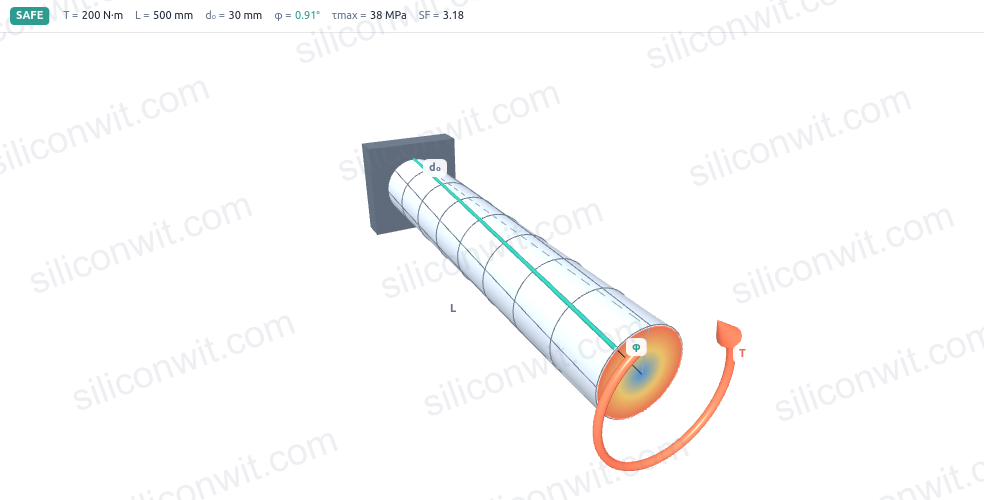
| description | Interactive 3D torsion of circular shafts: orbit a twisting shaft, see the shear-stress gradient across the radius (zero at the centre, maximum at the surface), read the angle of twist along the length, sweep the diameter against the allowable stress, compare solid against hollow, and check the safety factor, with downloadable data and a lab report. | ||||||
| contributors | sam-macharia | ||||||
| pubDate | 2026-06-05 | ||||||
| tags |
|
||||||
| excerpt | Orbit a 3D twisting shaft in your browser and watch the painted surface lines shear into helices while the end face shows the shear-stress gradient. Read the angle of twist, sweep the diameter against the allowable stress, compare solid against hollow, and download data, design specs, and a lab report. | ||||||
| heroImage | https://cdn.siliconwit.com/product-development/solid-mechanics-analyzer/shaft-torsion-diagram.png |
import TawkWidget from '../../../../components/TawkWidget.astro'; import UniversalContentContributors from '../../../../components/UniversalContentContributors.astro'; import InArticleAd from '../../../../components/InArticleAd.astro'; import Copyright from '../../../../components/Copyright.astro'; import BionicText from '../../../../components/BionicText.astro'; import TailwindWrapper from '../../../../components/TailwindWrapper.jsx'; import { Tabs, TabItem } from '@astrojs/starlight/components'; import { Card, CardGrid, Badge, Steps, LinkButton, FileTree } from '@astrojs/starlight/components';
import SolidMechanicsAnalyzerComments from '../../../../components/solid-mechanics-analyzer/SolidMechanicsAnalyzerComments.astro';
A shaft that passes the strength check can still fail in service: if it twists too much under load, gears lose their mesh, couplings bind, and timing-critical assemblies go out of phase. The allowable angle of twist is often around one degree per metre, which is a number that is impossible to picture on a drawing. This simulator lets you orbit a 3D shaft as it twists, watch the shear-stress gradient build from zero at the neutral axis to its maximum at the surface, read the angle of twist for any combination of torque and geometry, and see immediately how much material a hollow bore saves for how small a stiffness penalty. All four analysis views update as you drag any parameter. #ShaftDesign #Torsion #SolidMechanics
Open Simulator
See the linear shear-stress profile across the full radius: zero at the centre, maximum at the surface. A colour gradient on the 3D shaft and a chart across the section both show the same gradient. Read the total angle of twist and the twist per metre for any torque, length, and shear modulus. A chart plots the cumulative twist from the fixed end to the free end. Compare a hollow shaft against a solid one of the same outer diameter. Charts show what fraction of material and torsional stiffness you retain as the bore ratio increases. Sweep the outer diameter against the allowable shear stress to find the minimum safe diameter, and read a live safety factor and a verdict for your current shaft. 1. **3D orbit, zoom, and auto-rotate with exaggerated twist** The Three.js shaft renders painted surface lines that shear into helices as it twists. The displayed deformation is exaggerated so the twist is visible; the real angle reads on the charts.-
Live numerical readouts Peak shear stress, shear stress at the bore, polar moment J, angle of twist, twist per metre, surface shear strain, and the safety factor all update as you move any slider.
-
Four analysis charts in two tabs The stress-and-twist tab shows shear stress versus radius and angle of twist versus position along the length. The sizing-and-material tab shows peak shear versus outer diameter (with the allowable stress line) and the hollow-versus-solid material and stiffness curves.
-
Four shaft presets Solid steel, hollow steel, precision shaft, and aluminium shaft cover the most common starting points. Switch presets and the 3D shaft, charts, and summaries all update together.
-
A/B shaft comparison Save the current shaft as Shaft A, change any parameters (for example switch from solid to hollow), and the A curves overlay every chart as a dashed purple line so you can compare both configurations directly.
-
Diameter sweep The peak-shear chart sweeps the outer diameter from 10 mm to 90 mm at constant torque and bore ratio, with the allowable stress as a horizontal line. The intersection is the minimum safe diameter, read as a separate result.
-
Watermarked free exports and paid downloads Export any chart as a watermarked PNG for free. Paid downloads (1 USD each) include a watermark-free lab report with all four charts, a full CSV dataset for both shafts when comparing, and a design-data sheet with animation video.
| Preset | T (Nm) | L (mm) | d_o (mm) | d_i (mm) | G (GPa) | tau_allow (MPa) | Represents |
|---|---|---|---|---|---|---|---|
| Solid steel shaft | 200 | 500 | 30 | 0 | 79 | 120 | Typical steel transmission shaft, solid section |
| Hollow steel shaft | 200 | 500 | 36 | 26 | 79 | 120 | Thin-walled steel tube, same torque as solid preset |
| Precision shaft | 80 | 400 | 25 | 0 | 79 | 90 | Instrument or spindle shaft where twist is tightly controlled |
| Aluminium shaft | 120 | 600 | 35 | 0 | 26 | 70 | Lightweight aluminium drive shaft, lower G and allowable |
Polar moment of area for solid and hollow circular sections:
J_solid  = pi * d_o^4 / 32
J_hollow = pi * (d_o^4 - d_i^4) / 32
Shear stress at radius r from the centre (torsion formula):
tau(r) = T * r / J
tau_max = T * r_o / J       (surface, r = r_o)
tau_bore = T * r_i / J      (bore wall, r = r_i; zero for solid shaft)
Angle of twist over length L (in consistent units: T in N*mm, L in mm, G in MPa):
phi = T * L / (G * J)       (radians)
phi_deg = phi * 180 / pi
twist_per_metre = phi_deg / (L / 1000)    (deg/m)
Torque from power and angular velocity:
T = P / omega (P in watts, omega in rad/s, T in N*m)
Safety factor and minimum diameter check:
SF = tau_allow / tau_max
d_min = ( 16 * T / (pi * tau_allow * (1 - k^4)) )^(1/3)
  where k = d_i / d_o  (bore ratio; k = 0 for solid)
Hollow-versus-solid material and stiffness ratios (same outer diameter):
material ratio = (d_o^2 - d_i^2) / d_o^2  = 1 - k^2
stiffness ratio = J_hollow / J_solid       = 1 - k^4
Work through the Shaft Torsion Experiments lesson for structured, Python-verified exercises that use this simulator as the measurement instrument:
- Shear-stress distribution across the radius
- Angle of twist and torsional stiffness
- Sizing a shaft to an allowable shear stress
- Hollow versus solid at the same outer diameter
- Effect of material: steel versus aluminium
- Twist limit as the governing design constraint
- Shaft Torsion Experiments: the hands-on lesson that pairs with this simulator.
- Fundamentals of Shaft Torsion: the lesson that owns the underlying theory for this simulator.
- Combined Bending and Torsion Loading: how torsion combines with bending at a shaft surface, feeding directly into a Mohr's circle analysis.
- Solid Mechanics Analyzer: the full suite of stress-analysis simulators.
- Beam Analysis Simulator and Axial Loading Simulator: the neighbouring simulators in the suite.